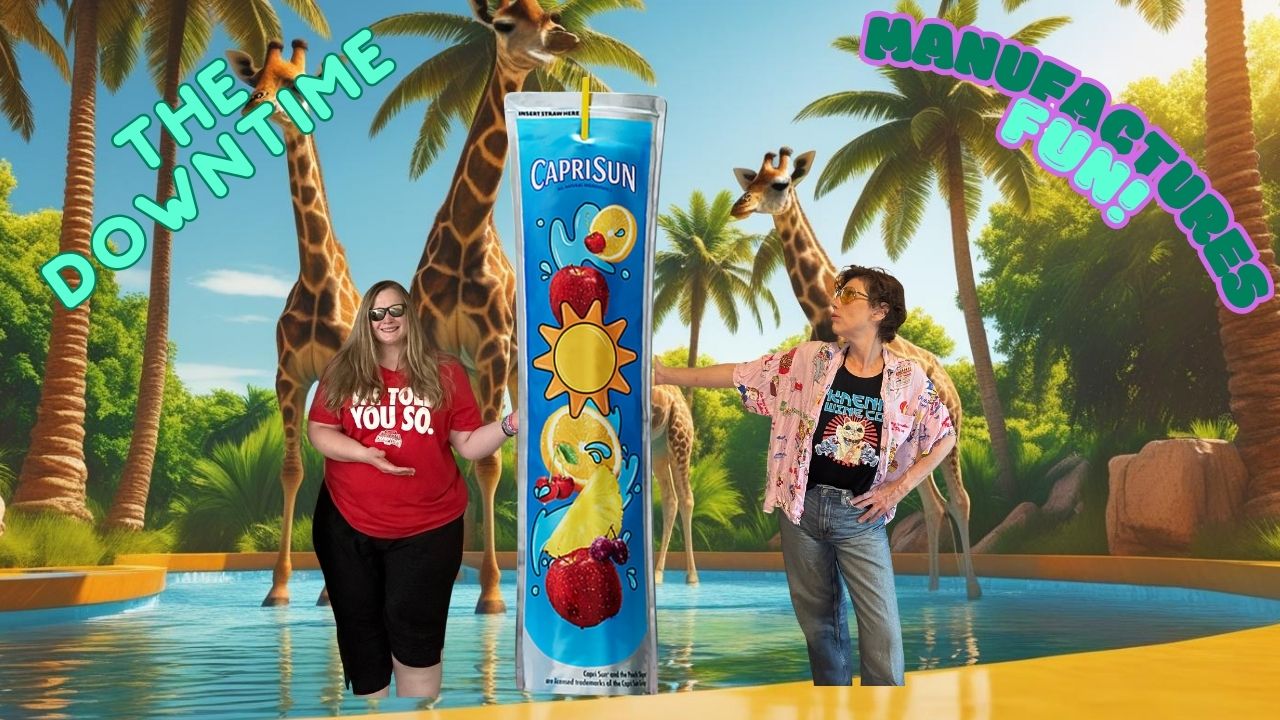
The Downtime Rewinding The Downtime: How to unpack Capri-Sun’s Solstice pouch, co-ops and automated packaging
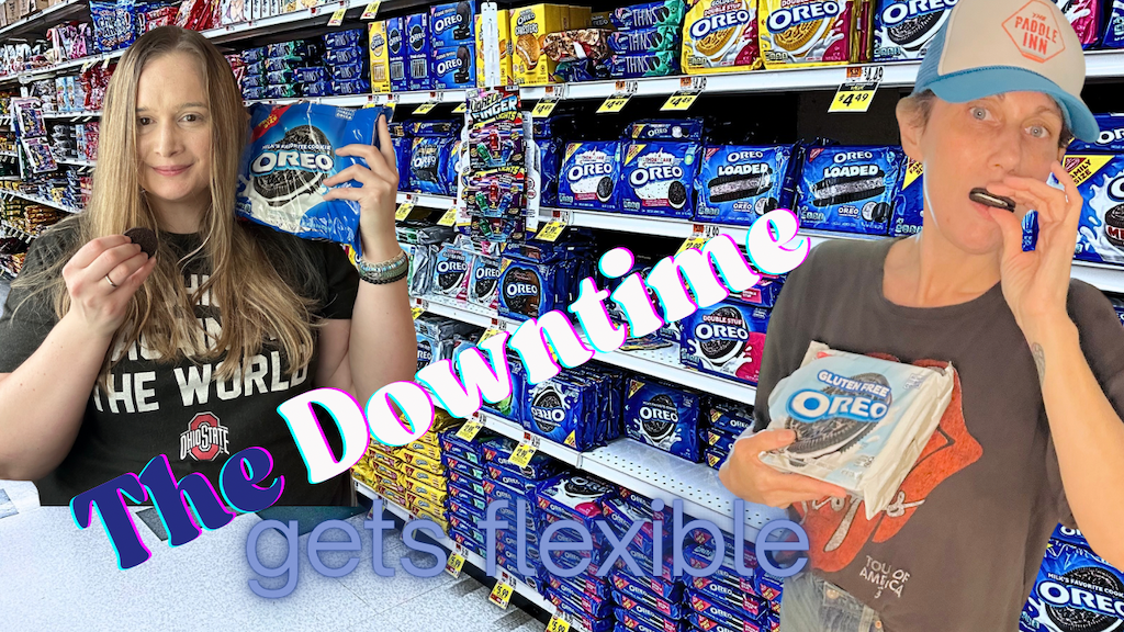
The Downtime The Downtime | Episode 9: Talking about flexible packaging, Purdue’s automated warehouse and new grads