
A seventh axis cobot transfer unit can aid in productivity. Here’s how.
Learning objectives
- Learn how deploying a seventh axis cobot transfer unit (CTU) can boost productivity.
- Weigh the pros and cons of mounting the CTU on the floor, wall or ceiling and the need for precise alignment.
- Explore other considerations for selecting seventh axis CTUs, including materials, collision detection capability and number of linear guides needed.
Seventh axis robotic insights
- Actuator-driven CTUs enable cobots to tend multiple workstations, maximizing return on investment in robotics.
- Proper mounting and alignment are critical to the success of a seventh-axis robot; built-in collision detection can enhance human and machine collaboration.
Six axes of robotic motion usually provide sufficient freedom for most applications. However, mounting a robot arm on a movable base — known as a seventh axis — adds flexibility, enhances collaboration and provides collision protection.
A seventh axis, also referred to as a collaborative robot (cobot) transfer unit (CTU) or range extender, consists of actuator-driven guide rails that carry the robot arm assembly from one task location to another.
Traveling productivity improvement with a seventh axis
CTUs are becoming increasingly popular for operations requiring multiple tasks, such as milling, lathes, testing, inspection and welding. Adding a seventh axis of motion enables one robot to perform various operations across multiple pieces of equipment or workstations (see Figure 1).
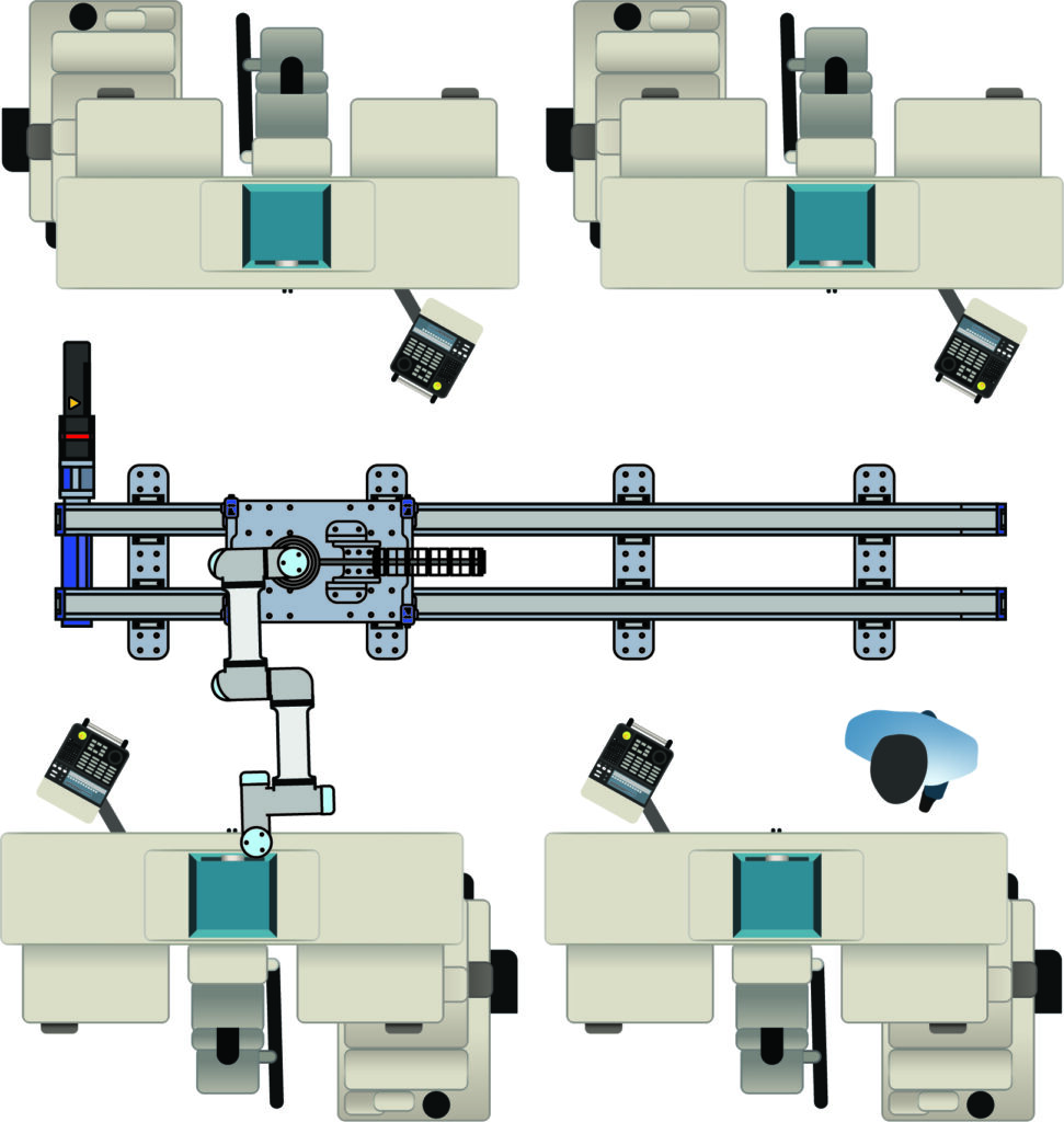
A robot equipped with a seventh axis, for example, could load one machine and then, while that machining cycle runs, move on to load another machine. This capability reduces the need to deploy multiple robots to accomplish different tasks.
A seventh axis is, however, a high-precision system and maximizing productivity from it requires close consideration of where and how you mount it and application-specific factors such as the availability of collision detection systems and the number of linear guides used.
Mounting orientation
CTUs are traditionally mounted horizontally on a table, wall or ceiling (see Figure 2). Table mounting is the most common orientation and likely the least expensive option. The table is usually made of steel or extruded aluminum that is secured to the floor, providing a solid base that is relatively easy to relocate and accommodate power and control cabling.

The downside of a table-mounted solution is that the assembly can obstruct operator access when human intervention is required for setup, monitoring or other purposes. Mounting the CTU on the ceiling or wall solves that problem.
If wall space is available, mounting the CTU provides better accessibility to the application than floor mounting. The wall must have adequate support or the ability to be reinforced. Wall mounting does, however, limit strokes to 16.4 feet because the drive belt may sag beyond that stroke length. Table- or ceiling-mounted systems, in contrast, can usually accommodate strokes of up to 32.8 feet.
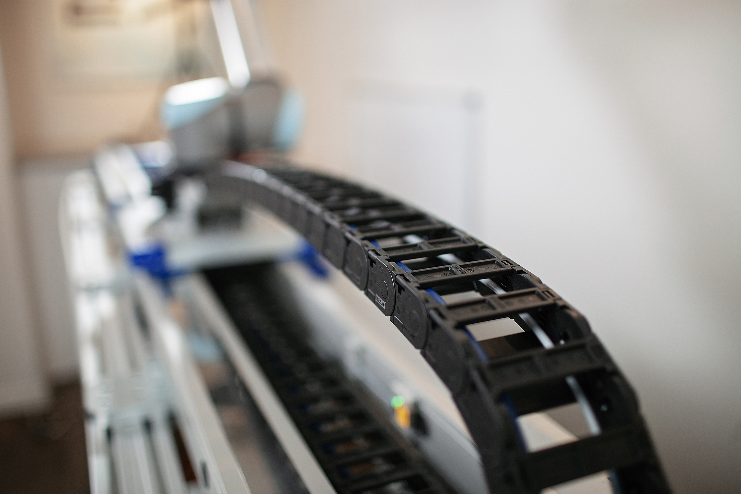
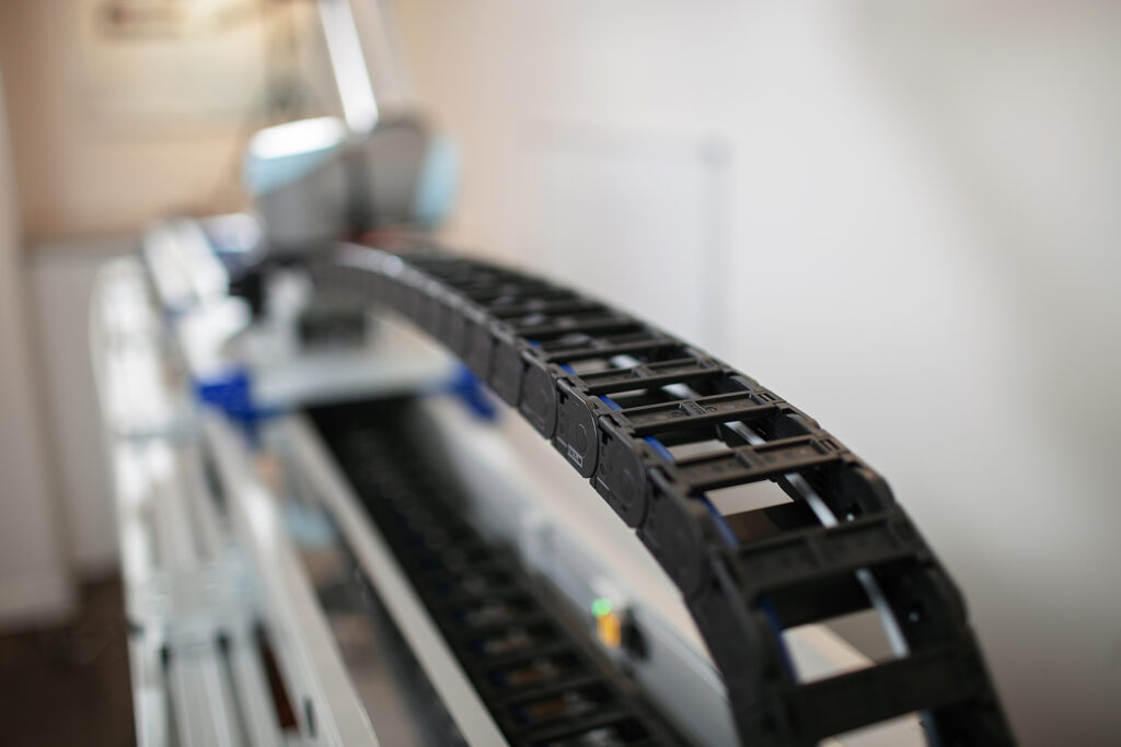
Mounting the CTU from the ceiling can provide operators with even greater access to the task area if steel stanchions, rigging or other structural supports are installed. You do, however, still must figure out what to do with the cables, which could otherwise hang into the task area. Some manufacturers use cable management trays, which keep the cabling out of the way (see Figure 3).
Material considerations
Although CTUs intended for light-duty operation might be mounted on extruded aluminum tables, steel tables provide the stiffest support with the least vibration. And, if the CTUs have collision detection capability on the seventh axis, the controls will stop or slow the robot’s movement upon contact with a human.
The stiffness and lower vibration of steel tables also afford greater sensitivity control, which helps to avoid nuisance trips. From a control tablet, users can adjust sensitivity settings to designate the level of human contact the cobot joints can endure before the system shuts down, thus avoiding nuisance trips based on incidental contact.
Consider seventh axis alignment issues
Regardless of mounting orientation, the flatness of the surface is critical to system performance. Baseplates typically sit between the CTU and the mounting surface unless the contact area has minimal surface variability (i.e., less than 0.004 inches/feet).
The system could interpret any misalignment as an unexpected load and halt operations immediately. Such misalignment can also contribute to excessive wear, which could negatively impact long-term life.
Seventh axis vendor manuals usually provide guidance on the degree of misalignment a unit can tolerate. Some vendors offer laser-guided alignment systems that mount onto the base plate. The laser alignment system measures the flatness optically and transmit the measurements onto a digital application, which calculates and returns the exact number of provided shims to add to the corners of each baseplate to comply with recommended alignment tolerances.
Doubling down
While single-rail linear guides may be acceptable for the smallest cobot sizes (6.6 and 11 pounds), for robots with payloads of 15 pounds or greater, a dual-guide system provides the proper moment load and stiffness that is typically required from applications like welding, machine tooling and material handling (see Figure 4).

Optimizing return on seventh axis robotics
By adding an additional axis to a traditional six-axis robot, cobots can support multiple process points with high efficiency. Whether installed on a table, wall or ceiling, the integrity of the installation affects the performance, durability and collision avoidance of the system. With less concern about collisions, either nuisance or real, manufacturers can deploy cobots to work more closely and flexibly with humans, minimizing nuisance trips and related downtime.
Manufacturers without experienced, in-house cobot integrators would be wise to consult with professional integrators to ensure optimal performance. A professionally installed CTU will maximize the return on investment in cobots through higher productivity and optimized collaboration among humans and machines.