Tips for preventing dc motor problems
Key concepts Early detection and correction of problems prevent expensive repairs. Maintaining commutators averts many problems.
Key concepts
Early detection and correction of problems prevent expensive repairs.
Maintaining commutators averts many problems.
Commutator contamination comes from brushes, dust, and chemicals.
When management decides that a plant can reduce maintenance costs 20%, it is the maintenance professional that is forced to do more with less. As a result, maintenance crews are always looking for better ways to manage their workloads. Since dc motors require more maintenance than their ac counterparts, they are good places to apply time and money-saving tips.
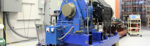
Maintenance personnel already change brushes in most plants (Fig. 1). Some also periodically check the condition of winding insulation with a megohmmeter. A few maintenance professionals even machine commutators in-place when downtime is not an option.
What else can a maintenance technician do to save money and avoid downtime? The following tips will help to quickly spot and remedy common dc machine problems. Early detection prevents small problems from growing into expensive repairs.
Normal commutator wear patterns
Even if a dc machine has been in service for just a short time, it’s fairly easy to judge its performance from the appearance of the commutator. As a result of normal commutation, current from the brushes vaporizes some copper molecules, depositing a copper-oxide film on the commutator surface (Fig. 2).
If the machine is performing well, this residue is about 0.2 millionths of an inch thick and has a uniform tan to charcoal-brown color. Faint charcoal streaks along the brush paths may also be present when a machine is performing well.
Slot bar marking and burning
An alternating pattern of light and dark bars on the commutator of a dc machine may or may not be cause for concern. It is related to the number of conductors per slot and caused by the first or last conductor in the slot passing under the brush before or after entering the field of commutation (Fig. 3).
The presence of certain factors (electrical overload, incorrect neutral setting, improper interpole strength, or contamination) can exacerbate slot bar marking and cause burning (Fig. 4). At that point, the trailing edges of the darker bars appear to be etched or burnt, indicating that it is time to resurface the commutator.
To avoid that result, identify and correct the underlying causes at the first sign of slot bar burning. Check the neutral setting and adjust it if necessary. Install split (multiplex) brushes to improve current distribution and decrease the amount of heat generated in the brushes. Check the interpole strength, or have a service center look it over if that check is beyond company expertise.
Streaking
Dark streaks along the brush path on the commutator surface, often found on machines with long-life brushes, indicate that metal is migrating from the commutator to the brushes (Fig. 5). This borderline normal condition can be caused by insufficient brush spring tension, too light of a load, or a brush grade that is too porous.
Contamination by chlorine, hydrochloric acid, silicon vapors, or other chemicals can also cause streaking. Remedying the underlying contributing factors early can prevent the condition from developing into a more severe stage called threading.
Threading
Threading describes the transfer of excessive amounts of metal to the brushes during commutation. It is evident when numerous thread-like marks form on the commutator along the brush paths (Fig. 6).
As with streaking, threading may be due to inadequate brush spring tension or too light a load. Other, less common causes include a brush grade that is too porous and chemical contamination. If the underlying cause is left unchecked, the condition gradually worsens, causing rapid brush wear and sometimes damaging the commutator beyond repair.
If threading is detected early enough, the commutator can be machined in-place to restore a smooth finish. Verify, or have a service center verify, that the diameter of the commutator is within tolerance. If the diameter is too small, heating increases and performance suffers.
Grooving
Another common wear pattern is grooving. This condition differs from threading because the grooves tend to be smoothly worn to the width of the brushes, and commutator material is worn away rather than transferred to the brushes (Fig. 7). Although grooving usually is due to abrasive dust in the environment, using a brush grade that is too abrasive can also cause it.
As grooving progresses, the sloped walls pinch the brushes, diverting much of the spring tension from the brush face. As the effective spring tension decreases, electrical resistance increases. This change generates more heat at the brushes and commutator. Unchecked, grooving may eventually lead to a flashover or arcing between brushholders, with serious damage to the brushholders and/or commutator.
At the first sign of grooving, check for and eliminate airborne abrasive dust. Corrective action may include adding filters or ducting in clean air from another location. In either case, maintain an adequate volume of airflow.
If grooving progresses too far, the only solution is to replace the commutator. That action requires an armature rewind and time-consuming repair.
By keeping a close watch on the condition of dc machines, maintenance professionals can spot developing problems. Correcting them during normally scheduled maintenance means the motor does not have to be removed from service unnecessarily, saving time and money. Changing weak brush springs is a lot less trouble than replacing a motor. Correcting a problem air supply means the replacement lasts longer.
Issues such as minimum commutator diameter, accurate turning and undercutting of the commutator, precision balancing of armatures, and use of flashover-reducing materials on the commutator string-band are often beyond the capabilities of plant maintenance shops and should be referred to a qualified service center.
—Edited by Joseph L. Foszcz, Senior Editor,
630-320-7135, jfoszcz@cahners.com
More info
The author is available to answer questions about maintaining dc motors. He can be reached at 314-993-2220, fax 314-993-1269, or e-mail cyung@easa.com.
Contamination sources
Silicone
Environmental contamination, especially gases that attack copper, adversely affect commutation, causing problems for dc machines. Most technicians dealing with dc machines are aware of problems stemming from chlorine and hydrochloric acid. Some even know about the problems the U.S. Navy had with silicone in the late 1970s, before manufacturers offered an alternative "electrical grade" silicone with a different curing agent. Unfortunately, there is no way to tell which type of silicone was used to seal the ducts that supply air to a dc machine.
Hydrochloric acid
An unexpected source of contamination is affecting the paper industry in some regions, where efforts are under way to eliminate dioxins from the waste stream. An unfortunate byproduct of the new process is hydrochloric acid—which is much more detrimental to a commutator than chlorine.
Abrasive dust
Abrasive dust means trouble for dc machines, causing grooves to develop much more quickly along commutator brush paths. All plants with dust in the atmosphere are susceptible. Filtered air helps, but is not always practical. Ducting in outside air may be a solution, but only if clean air is available nearby. Long ducts reduce air volume, creating other problems.
Plastics
When a plastic melts near the operating temperature of a dc motor, clogged vent passages are only one result. Melted product can build up on the motor exterior, trapping heat and shortening insulation life. For every 18-deg F above the winding’s insulation rating, insulation life is cut in half. If the temperature is 72 deg F above the rating, for example, the insulation will last only 1/16 of its design life.
Plastic can also cause brushes to stick in their holders. When this happens, brush pressure drops as the brushes wear. The spring pressure remains constant, but can’t move the brush in the holder. As the brush continues to wear, contact pressure decreases until the inevitable flashover occurs.
Brush maintenance tips
Many common commutation problems stem from improper brush spring tension or use of the wrong brush grade. The following tips help in setting brush spring tension and selecting the proper brush grade.
Brush spring tension and pressure
Too little spring tension is worse than too much. Insufficient spring tension causes higher resistance across the brush-commutator connection, resulting in excess heat and decreased performance.
It is easy to measure and, if necessary, correct brush spring tension. Spring scales for this purpose are available from most brush manufacturers—or use a good fish scale.
To measure spring tension, attach a spring scale to the brush shunts and pull directly in-line with the brush being checked. When the brush lifts away from the commutator, slowly release tension until the brush starts moving down. The pressure indicated on the scale at that point is the spring tension.
Next, calculate the brush pressure in pounds per square inch (psi). Multiply the thickness of a single brush by its width (in inches) to find the square area of brush surface. Then divide spring tension by the brush area to get the brush pressure.
For most applications, brush pressure should be 4—6 psi. Traction motors, because they are subjected to higher vibration levels, usually perform better with a brush pressure of 6—8 psi.
A common cause of weak springs is loose connections at the bolted brush shunt connection. Springs are not intended to carry current and quickly lose tension when they do. Replace weak springs promptly.
Current density and brush grade
Once the brush area is known, check the current density of the brushes and the actual load of each motor application. This check helps determine the correct brush grade for each motor.
Each carbon brush grade is designed to carry a specific current density. It is important to know the brush grade being used, as well as the actual load for each motor, when evaluating brush performance. High current density increases the operating temperature of carbon brushes. Too high a current may also damage the brush shunts. Current density that is too low is worse. Low current density causes rapid brush wear. In extreme cases, brushes can wear out in a matter of days.
To determine current density, measure the cross-sectional area of the brush surface. Think of the brushes as a group of series-parallel conductors. Since half of the brushes constitute a parallel path for the armature current, the total armature current is shared among those brushes. If each brush measures 3/4 in. 3 11/2 in., and the motor has 24 brushes, the brush area is: 3/4 in. 3 11/2 in. 3 12 = 13.5 sq in.
For a dc motor rated at 742 amps, the current density of the brushes works out to 55 amps/sq in. (742/13.5 = 54.96). That figure is in line with the current density rating of many carbon brush grades.
But what happens if the motor is only loaded to 400 amps? Now the current density drops below 30 amps/sq in. (400/13.5 = 29.62). With many common brush grades, that is too low. The brush wears rapidly, the motor fills with carbon dust, and motor performance suffers. It is essential to base the calculations on actual current, rather than nameplate current.
A simple trick to increase brush current density is to remove half of the brushes from the machine. When doing this, it is vital that the same brush position be removed from each brushholder row. For applications where the motor load may vary depending on production levels, removing part of the brush compliment allows the maintenance technician to tune the motor for its load. When a change is made to a heavier product, the brushes can be reinstalled. For a load that varies frequently, it may make more sense to discuss the range of loading with a brush supplier. There are brush grades suitable for a wide range of current densities.
Electrical balance
Brushes also play an important role in keeping the machine electrically balanced. Brushes of negative polarity deposit material on the commutator, while those of positive polarity remove material. The rate of deposit must equal the rate of removal. To maintain this balance, there must be an equal number of positive and negative brushes in each circumferential brush path.
Work with the carbon brush supplier to survey the brush grades of each motor application in the plant. Document the preferred brush grade for each motor, and keep spares on hand. Don’t fall into the trap of grabbing brushes from another bin just because they have the same dimensions. DC machine performance suffers when brush grades are mixed.
Do you have experience and expertise with the topics mentioned in this content? You should consider contributing to our CFE Media editorial team and getting the recognition you and your company deserve. Click here to start this process.