How fluid vessel types and other variables influence system design
Grab sampling plays a key role in many refineries and processing plants around the world, helping operators maintain quality control, regulatory compliance and assurance that products are up to specification. The process is performed by capturing a sample in an appropriate container, then transporting the sample to a remote laboratory for analysis.
Samples must remain representative of process conditions from the point of capture through analysis to ensure accuracy. Yet, certain grab sampling system design choices can highly influence sample integrity and therefore the accuracy of readings. This article will review some practical tips to help grab sampling technicians maintain accuracy, including important considerations for system designs and sampling vessel choices.
Specifying systems
Grab sampling system designers must first consider the type of vessel to be used for sample transport. The choice is typically between a glass or polyethylene bottle, or a sealed metal cylinder.
A few factors determine this choice. Bottles cannot contain pressure, for example, and can only be used for liquid samples. By contrast, cylinders can maintain pressure and are appropriate for liquid or gas samples. See Table 1 for a quick reference.
Other important design considerations include:
- System Pressure. Grab sampling systems have a maximum pressure rating – and it is important that designers do not exceed that pressure for safe operation. For chemicals that may rapidly expand and pressurize under temperature changes, consider using a rupture disc or relief valve.
- Systems also have a maximum temperature rating. Exceeding that rating can damage seats and seals in the system. Importantly, systems also have a minimum operating temperature, which helps ensure the fluid flows at a sufficient rate for timely analysis.
- Material Compatibility. A process fluid and the grab sampling system itself must be compatible with each other, or else corrosion issues can occur. Most systems are built with 316 stainless steel, but some system requirements may call for higher-performing alloys such as 400 and C-276 to ensure compatibility and eliminate corrosion issues.
- Purging Needs. Regular system flushing helps fight against contamination and corrosion, so be sure to add a purge setup for removing residual process fluids from grab sampling system lines.
System designers should be sure to think through each of these considerations when specifying a grab sampling system for their facilities.
Sampling with cylinders
Numerous options are available for gas or liquid sampling with cylinders. One common, highly efficient design is a closed-loop system, which draws a sample from a positive-pressure process and returns it to the process at a lower-pressure location. This system uses differential pressure to drive the fluid through the sample system. The sample continuously circulates through the cylinder while the operator takes a sample.
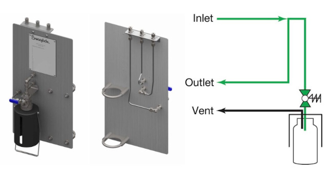
Closed-loop systems reduce the need for purging because the sampling system effectively becomes an extension of the main process system. When the grab sampling system inlet valve is opened, process fluid flows through the system and the sample cylinder, then flows out to the outlet port (see Figure 1). Older process fluid remaining in the short inlet line will be flushed through the closed-loop path, returning to the main process system as the cylinder fills.
Figure 1: This design is for sampling a gas without a separate purge line (1a). With the sampling system valves and the cylinder valves open (1b), process fluid flows through the cylinder and returns to the main process. When retrieving a sample, the operator will close the cylinder valves and turn the system to vent to isolate the supply/return lines and allow the fill lines to vent (1c). The operator will then turn the system off before disconnecting the cylinder. Courtesy: Swagelok
Operators can simply close the cylinder’s inlet and outlet valves and turn the system to vent when the sample is ready for removal. Then, they can close the system’s inlet valve to stop the flow and remove the cylinder for transport to the lab. Inside the cylinder, the sample remains under the same process conditions, except for temperature, and as a result should be highly representative of the main process itself.
Though cylinders can be used for gas or liquid samples, there are some critical distinctions for each. Most importantly, flow paths should be different for gases and liquids to enable the purging of any out-of-phase fluids from the cylinder, as follows:
- Gases should flow from the top of the cylinder down (as shown in Figure 2a), pushing out any liquid or condensate from the sample cylinder as it fills. This ensures liquid will not collect in the cylinder and interfere with analyzer readings.
- Liquids should fill from the bottom up (shown in Figure 2b). This helps displace the vapor space and ensure the cylinder is full. An outage tube can be added to cylinders capturing liquid samples to maintain expansion space in the cylinder, as the trapped vapor may compress under pressure. (see the “Outage Tubes Explained” sidebar).
Figure 2: When using cylinders, gas samples (2a) should flow from the top down to push out any liquid or solid as the cylinder fills. Liquid systems (2b) should be designed to fill from the bottom up, so the sample displaces the vapor space. Courtesy: Swagelok
Of course, safety is important here, too. Ensure that any cylinders used for gas or liquid samples comply with all appropriate safety regulations.
Bottle sampling in liquid applications
Liquid-only grab sampling using bottles involves drawing fluid directly from the process into non-pressurized bottles. Bottle sampling can be a more economical solution in suitable applications, and the clear glass structures are good for immediate visual checks on quality.
Bottle sampling is a good choice for process fluids that are not susceptible to fractionation or evaporation when the sample is at atmospheric pressure. Note that any increase in internal pressure may cause loss of sample through the lid or septum cap seal – accordingly, liquid bottle systems should be used with water or other low-vapor-pressure liquids.
In suitable applications, first determine whether continuous flow and purging are required. Continuous flow comes in handy when the sample requires constant motion, or when a long tubing run leads up to the sample point. Under a continuous flow regimen, the sample flows through a bypass loop in the grab sampling system and avoids sitting in tubes for extended periods, ensuring the sampled fluid remains representative. The sample bottle is then filled using a spring-loaded sampling valve (shown in Figure 3). A purge assembly should be used if the sampled fluid has the potential to solidify, as it will help the dispensing needle and internal tubing stay clean.
Figure 3: This bottled grab sampling system design (3a) is used when continuous flow is required from inlet to outlet. When the operator opens the spring‐loaded sampling valve (3b), process fluid flows into the bottle, while also continuing to flow through the bypass. Courtesy: Swagelok
Fixed-volume systems are advantageous if the liquid is highly pressurized or hazardous. This type of system effectively isolates the user from process pressure while limiting the fluid volume dispensed. Here, the sample first fills a metal cylinder before being gently pushed into a sampling bottle by a low-pressure purge gas, helping to protect against inadvertent overfilling.
When it comes to safety, liquid samples may need to cool before operators are able to safely fill and retrieve a bottle without risking burns or injuries.
Ensuring success
Careful selection of container type and proper configuration of other system variables can help any industrial operator maintain sample integrity. The key to accurate analysis is ensuring the captured sample is representative of process conditions when collected and analyzed. By following the tips in this article, designers and operators can achieve more efficient, accurate, and safe analyzer results from their grab sampling systems.
Outage tubes explained
Outage tubes (Figure 4) can be used as a safety mechanism in liquid cylinder sampling. An outage tube enables a defined volume of vapor space to stay inside the cylinder while capturing a sample, allowing the liquid to expand if temperature increases. Without enough space, a small temperature increase can cause liquid expansion and dramatic pressure increases, which can compromise operator safety.
The length of the outage tube determines the amount of vapor space, per the calculation % Outage = (Vapor Space/Total Volume) x 100.