Process piping system design is a complex and involved process that has a significant impact on many industrial facilities. Nine crucial aspects for design are highlighted.
Learning Objectives
- Understand the role process piping system design plays in industrial facilities.
- Learn about the nine aspects all engineers should consider when designing a process piping system.
- Understand the intricate steps involved in each step and the complex factors they need to consider.
Piping system design insights
- Process piping systems are essential in various industries, including chemical plants, refineries, and food processing facilities. They ensure efficient transportation of fluids, improving safety and productivity while minimizing downtime.
- Effective design involves selecting suitable materials, pipe sizing, and layout. Considerations include fluid properties, pressure ratings, thermal expansion and environmental factors, ensuring durability and compliance with industry standards such as API and ASME.
- Incorporating features for easy maintenance, accessibility, and compliance with safety standards like OSHA is crucial. Proper valve placement, labeling, and inclusion of safety devices like pressure relief valves and emergency shutdown valves enhance operational reliability and safety.
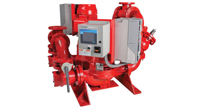
Process piping refers to systems of pipes that transport fluids around industrial facilities. Chemical and petrochemical plants, oil refineries, power plants, pharmaceutical manufacturing facilities, food processing and water treatment plants are among the places where process piping is found. Less obvious industries such as automotive, mining, agriculture, residential and healthcare also use process piping. Process piping may not always be seen, but it is a critical component in many industrial settings.
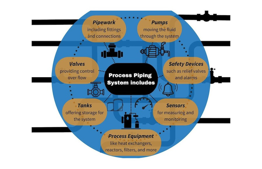
Process piping systems are networks of interconnected process piping, process equipment, pumps, tanks, valves and fittings that work together to accomplish a specific task or sequence of operations. Components of a process piping system include:
-
Pipework, including straight pipe sections, pipe fittings and connections
-
Motive equipment such as pumps or blowers
-
Flow control devices such as valves
-
Storage equipment such as tanks
-
Process equipment such as reactors, boilers and heat exchangers
-
Measuring and monitoring equipment
-
Safety devices such as pressure relief valves and alarms.
Process piping system design
Optimum design of process piping systems is crucial to the success of industrial operations. A well-designed process piping system operates efficiently and trouble free, with reduced downtime. It is safe to construct, operate and maintain; and is cost-effective, considering both upfront and life cycle costs. Optimally-designed process piping systems ensure:
-
Efficient transportation of materials within a process
-
Decreased risk of downtime
-
Improved safety for personnel and equipment
-
Effective control of operations leading to enhanced productivity.
When designing a process piping system, it’s vital that engineers consider these nine aspects.
1. Understanding the process
The first step in designing a process piping system is developing a comprehensive understanding of the process. This involves two aspects: Identify the specific industrial process and determine the process requirements.
Identify the specific industrial process
Each industry has unique processes which influence the design, installation, and maintenance of process piping systems. Depending on the industry, the processes involved and prevailing industry regulations, the piping system design will vary. For example, consider the differences among an oil refinery, water treatment plant and food processing facility:
-
Oil refinery: The process may require pipes resistant to chemical corrosion, high pressures, temperatures, and capable of handling highly viscous fluids. Codes, standards and guidelines from organizations such as the American Petroleum Institute (API) and the American Society of Mechanical Engineers (ASME) may be used in the design.
-
Water treatment: The process may necessitate pipes that can withstand aggressive environmental conditions, and be safe for potable water applications. The American Water Works Association (AWWA) standards may be incorporated in the design.
-
Food processing: High sanitary designs are required to avoid product contamination. The Food and Drug Administration (FDA) regulations and National Sanitation Foundation (NSF) standards may apply to such an installation.
Determine the process requirements
The next step is defining the process requirements, which can be categorized as performance requirements and safety requirements. Some examples are given below:
-
Performance requirements outline the parameters the piping system is designed for. This may include the flow rate, pressure and temperature range at all stages of the process.
-
Safety requirements outline the safety features of the process piping system. High or low flows, pressures or temperatures must be allowed for in the system design. Designs must be compliant with Occupational Safety and Health Administration (OSHA) standards, as well as the OSH Act.
Understanding the process ensures a process piping system is designed for the specific needs of the process, resulting in an efficient, safe and long-lasting solution.
2. Selecting piping material
Choosing the right pipe material is a critical step in process piping design. Each industrial process has particular requirements, necessitating careful consideration when selecting a pipe material. With so many materials available in the market, selecting the right one can be challenging.
Compatibility with process fluids
Material compatibility extends the life of a process piping system, and avoids contamination of the process fluid. The selected pipe material should be non-reactive with the fluids being conveyed. Fluids such as process chemicals, fuels and even water can be corrosive, resulting in damage to pipework, leakage, pipe rupture and other safety issues. Designers should examine chemical compatibility charts for suitable pipe materials, and ensure the pipe material will not corrode or contaminate the process fluid.
Operating and environmental requirements
The material selected for a process piping system must be capable of withstanding operating requirements, such as the operating pressure and temperature range. Environmental factors must be considered, as well — these depend on the specific industrial process and the environment in which the pipe system is installed. Consider the following:
-
The pipe material’s pressure-temperature rating.
-
Thermal expansion and contraction characteristics of the material under operating and environmental temperature ranges.
-
Pressure surges and phase changes which may occur.
-
Exposure to external elements such as rain, wind, snow, UV radiation.
-
Installation details such as buried pipe, submergence in seawater or acid.
Cost and availability
Another significant consideration is budget and availability. The selected piping material must align with budgetary constraints and be available when needed. Procurement delays can have a major impact on project timelines. The following aspects are important:
-
Compare the cost-effectiveness of different piping materials.
-
Verify the availability of the chosen material in the local market.
-
Consider the total cost of ownership (TCO), which includes the initial cost, installation cost, maintenance and replacement cost, if necessary.
-
Consider the design life of the process and plant and select accordingly.
3. Pipe sizing and layout
Correct pipe sizing and optimal piping layout are essential features of a well-designed process piping system. There’s much more to consider than just connecting pipes.
Determine pipe size based on flow rate and pressure drop
Piping must be sized to accommodate the flow rate and pressure loss for the industrial process. A pipe sized too small can lead to high velocity and large pressure drop, compromising the efficiency and performance of the process. However, a pipe sized too large can result in greater expenses due to the increased cost of piping, fittings, valves and ancillaries. When determining the pipe size and pressure drop in the system, consider the following:
-
Fluid properties: The type of fluid in the pipe, its temperature, density and viscosity impacts the pressure drop.
-
Pipe size: The velocity and friction in the pipeline are directly related to the pipe size, particularly the pipe internal diameter (ID).
-
Pipe length and fittings: Longer pipes and a greater number of bends and fittings increase friction, impacting the pressure drop.
Optimize the piping layout
Designing a simple and efficient layout for the process piping system promotes optimal performance, by reducing the material cost of the system and decreasing the energy required for the system to operate. Ensuring accessibility for routine maintenance and potential repairs prevents extended downtime that might otherwise affect productivity. An efficient layout should:
-
Minimize pipe length and number of fittings to reduce friction and minimize energy requirements.
-
Avoid sharp bends because they can cause flow disruption and pressure loss; sweep elbows are a better option.
-
Provide access for operational activities, inspections, routine maintenance and repairs.
-
Plan for future maintenance and expansion.
4. Pipe support
Pipe supports are an essential component of process piping systems. There are a wide range of options to choose from, from small clamp type supports to massive pipe racks carrying numerous pipes across an industrial facility. Pipes may sag or vibrate without adequate support. This can lead to accelerated corrosion, wear, fatigue and eventually failure. The following factors should be considered:
-
Use appropriate supports for the material and size of the pipe. These might include clamps, brackets, stands or racks.
-
Select a pipe support based on the desired pipe movement and degree of freedom required.
-
Ensure the pipe support system caters for the full range of anticipated loading conditions. These include the weight of pipe and fluid, friction between the pipe and support, pressure and surge loads during operation. Additional loads which need to be considered include thermal, wind, ice and seismic loads.
-
Account for pipe contraction and expansion. Support selections should accommodate thermal expansion and contraction to prevent damage. Pipe expansion loops or expansion joints may be required.
-
Pipe supports must be optimally spaced.
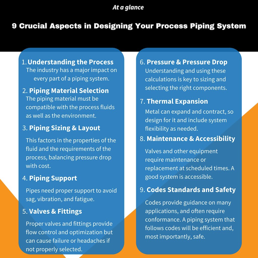
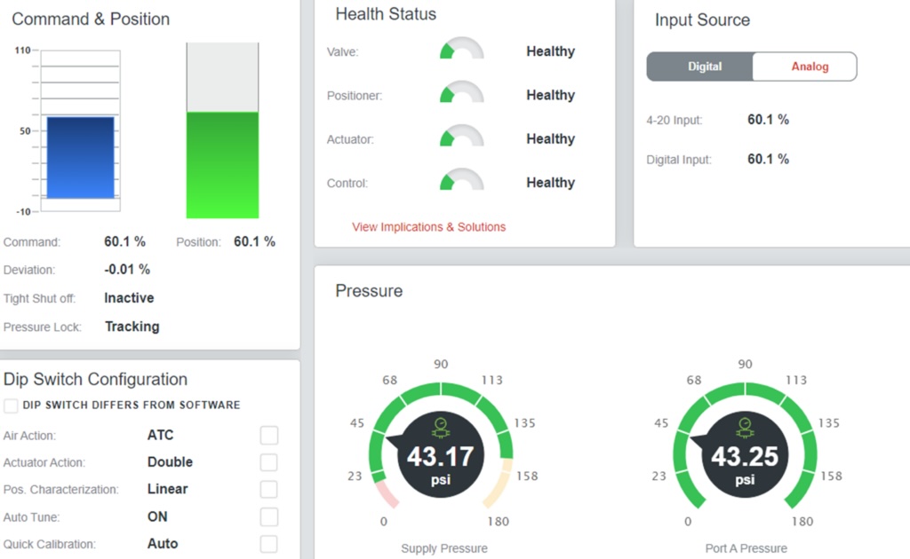
5. Valves and fittings
When designing a process piping system, the type and position of valves and fittings are an important consideration. Valves and fittings play a pivotal role in regulating the flow of fluids within a process piping system.
Selecting the appropriate valves for process control
Valve selection is a topic in its own right. The valve selection process should be rooted in a deep understanding of the process piping system’s overall functionality and the varying operational requirements. There are many different types of valves and each offer distinct benefits and are the optimal choice for specific applications. For example:
-
Gate, ball and butterfly valves are suitable for isolation.
-
Check valves prevent backflow.
-
Globe valves are a good choice for flow regulation and control.
-
Pressure relief valves protect the system from exceeding pressure limits.
Flow requirements, pressure ratings and material compatibility
There are several factors to consider when selecting valves and fittings for a piping system. Some common factors include:
-
Flow requirements — Dictates the size and type of valves and fittings necessary.
-
Pressure and temperature ratings — This ensures chosen components can withstand the system’s operating conditions.
-
Material compatibility — Selected valves and fittings should be composed of materials suitable for the application, thus avoiding corrosion, leaching or contamination of the process fluid.
6. Understanding system pressure and pressure drop calculations
Effective process piping design requires an accurate assessment of flow and pressure throughout the system, for all operating scenarios. Pressure drop refers to the reduction in fluid pressure as fluid flows through a pipeline.
Understanding the concept of a pressure drop
Pressure decreases in a piping system due to frictional losses as the fluid moves along the pipe’s length, encountering obstacles such as pipe walls, valves, bends, strainers, filters, other fittings or equipment. Pressure also will decrease as the fluid moves to a higher elevation in the system. Implications of high pressure drop in a process piping system include increased energy requirements, larger motive equipment and associated capital and operational expenditure.
Calculating pressure drop and selecting the right pipe size, valves and fittings
Calculations for pressure drop in piping systems are multifaceted and require technical know-how. Parameters such as fluid density and viscosity, pipe length, pipe diameter and flow velocity significantly influence the pressure drop in a process piping system. Other factors such as fluid elevation, pipe roughness and losses through fittings and equipment also must be accounted for.
Read up on the Bernoulli equation, Darcy-Weisbach equation and Colebrook-White equations for additional information.
Pressure drop calculations are crucial in specifying process equipment such as pumps, and optimizing pipe size. Be sure to consider the following:
-
Pipe size: Larger pipes minimize pressure drop due to reduced flow velocity. Conversely, smaller pipes lead to increased friction and greater pressure drop.
-
Pipe length: A longer piping system results in greater frictional losses and higher pressure drop.
-
Pipe roughness: Pipe which is rough internally will result in greater friction and increased pressure drop.
-
Component-induced losses: Fittings such as bends, reducers, valves, and strainers have a marked impact on fluid flow and pressure along a pipeline.
If the user has the technical know-how, a manual analysis of process piping system hydraulics may be conducted. Spreadsheet software is also a useful aid in automating the analysis. Numerous software systems are available to aid in analyzing process piping system hydraulics, helping specify the correct process equipment and the optimal pipe size.
7. Thermal expansion
Effective design of a process piping system requires an understanding of thermal dynamics and pipe flexibility. As temperatures change, piping could potentially expand or contract. Overlooking this aspect can lead to serious problems such as leaks, pipe ruptures or even system breakdowns.
Addressing thermal expansion and contraction issues
When dealing with long pipe lengths or extreme temperature ranges, the strain in the pipe due to thermal expansion and contraction is a major concern. Steel pipes, for instance, can expand and contract significantly with temperature change, resulting in significant stresses within the pipe wall. Here are a few points to consider:
-
Predict anticipated temperature ranges the piping system will be exposed to, due to both ambient and process temperature changes.
-
Understand the thermal properties and characteristics of the pipe material planned for use.
-
Ensure the design caters for and guides the anticipated movement of the piping due to thermal effects.
Incorporate expansion joints for piping system flexibility
One way to avoid detrimental thermal effects in a process piping system is providing flexibility. This may take the form of pipe expansion loops or expansion joints. Expansion joints may be specified with various degrees of freedom, allowing pipes to move axially or rotate without placing undue stress on the system. Take note of the following:
-
Provide expansion loops or expansion joints at strategic locations, like points where the pipe changes direction or at long overland pipe sections.
-
Incorporate flexible pipe components such as bellows for an adaptable pipe system.
-
Design piping layouts with a degree of flexibility, allowing for slight shifts in pipework without significant detriment to the system.
Piping designers often need to find a balance between pipe stiffness and flexibility, through the careful selection and placement of pipe supports, pipe fittings and making provision for pipe expansion.
8. Maintenance and accessibility
Maintenance is a critical factor in any industrial operation. Designing process piping systems for ease of maintenance and operational accessibility should be high up the list of priorities. A well-maintained and easily accessible piping system can save time and effort, reduce costs, and lead to operational efficiency.
Design for easier maintenance and component access
A process piping system should be designed so key components can be reached for operational and maintenance activities. Routine maintenance tasks, equipment checks, cleaning and repair activities should be hassle-free. Helpful features include:
-
Removable piping sections or the provision of flanges to provide access to valves and equipment
-
Component layouts that eliminate the need for excessive dismantling during maintenance. The use of dismantling joints, unions or flange adaptors may assist in this regard.
-
Provision of staircases, platforms and routes for easy access and operation of critical equipment.
Valve placement, pipe labeling and clearances
The process piping system design should not overlook factors like valve placement, pipe labeling, and clearances. Valve location directly impacts the ease of operation and maintenance processes. Proper pipe labeling is essential for safe and efficient pipe identification and operations, especially in complex systems. Pipe color coding, stenciling of pipe or product names, and flow directional arrows are a few examples.
Adequate clearances should be provided to ensure ease of inspection and repairs. These may include sufficient above-ground clearance, trench widths for underground pipes, and distance between pipe, valves and any obstructions. Access requirements and clearances for forklifts, cranes, trucks, rigging and lifting points must also be considered.
9. Codes, standards and safety considerations
Process piping systems must adhere to applicable codes and standards to ensure safety and reliability. They outline mandatory requirements and provide guidelines regarding the design, fabrication, quality control and testing of process piping systems and their components.
Ensure process piping system design adheres to established codes and standards, and encompasses the proper evaluation of safety requirements. This necessitates:
-
A thorough understanding of the nature of industrial processes, fluids and materials to be used — including their toxicity, combustibility and reactivity.
-
Compliance with industry-specific codes, for example the ASME boiler and pressure vessel code, and the ASME B31.3 – Process Piping code. These codes prescribe standards for pipe, fittings, valves and process equipment, amongst many others.
-
Compliance with applicable local, state and federal regulations, which help ensure worker safety as well as the environment.
Incorporating safety features
Safety considerations should be prioritized in the design of process piping systems. These include safeguards for the labor force, and precautions to protect against critical system failures. It’s a good idea to incorporate safety features within the piping system design. This may include:
-
Pressure relief valves, which automatically release fluid once the pressure in the valve exceeds a preset pressure limit. A variation called thermal relief valves release fluid to cater for thermal expansion of the fluid. Relief valves prevent over-pressurization, potential leakage, rupture or catastrophic failure of the pipe system.
-
Bursting discs, also called rupture discs, provide an escape route for over-pressurized fluid. The discs burst open at a pre-set pressure, allowing the fluid to escape and preventing damage to equipment or potential harm to the workforce. Bursting discs need to be replaced after each failure event.
-
Emergency shutdown valves (ESD) are actuated valves designed to stop the flow of fluid if a hazardous scenario is identified. ESD valves may be activated via a control system, or manual intervention.
Codes, standards and safety considerations play a vital role in the design of process piping systems. By adhering to these guidelines, engineers can ensure a system’s safety, reliability, and efficiency while mitigating potential hazards and risks.
Designing a process piping system is much more than building a network of pipes. Thoughtful and meticulous design ensures the system functions optimally, safely, and efficiently, directly contributing to industrial process performance. By focusing on the nine design aspects discussed, users can ensure improved productivity, secured operation and long-term value.