Stepper motor systems deliver more precision than standard variable-speed motors without the expense and complexity of servo motors, and newer high bus voltage options provide additional flexibility. See 5 motor technologies, common uses.
Learning Objectives
- Five motor technologies, common uses.
- When to use a stepper motor versus servo motor.
- Wider applications for steppers motors.
New stepper motor technologies can be applied to more applications than before and at a lower cost than other options. Almost every industrial machinery application involves creating and controlling motion of some type. As designers consider price and performance requirements, pneumatic options can be a good low-cost choice and hydraulics can deliver the ultimate amount of force. However, the most versatile motive force is some form of electric motor.
For industrial applications, the term motion control is generally understood be mean more than just spinning a motor to create motion. True motion control usually involves using some form of actuation to accurately command the position, velocity, and/or acceleration of equipment elements.
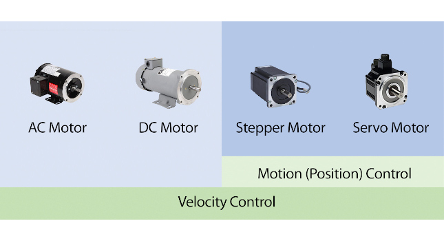
Standard ac induction motors and dc motors are best for simple on/off and continuous operation at fixed or varying speeds, but they are not ideal for positioning and fine control. Servo controllers, drives, and motors deliver exceptionally high performance for all types of motion control, but their complexity drives up engineering and procurement costs (Figure 1).
Stepper motors occupy a sweet spot, offering greater control precision than standard ac induction or dc motors at a cost far below servo solutions. Stepper motor systems have some limitations, but newer high voltage bus versions overcome some of those issues and make the technology a viable choice for more applications. This article identifies when a stepper motor system can be the best motion control solution.
5 motor technologies, common uses
Specifying any electric motor system involves understanding the load and how it needs to be moved in terms of force, speed, and accuracy. Durability and initial/operating costs also are important. Some of the most common types of motors for industrial applications are:
- AC induction: Available in a wide range of form factors and horsepower ratings, suitable for general applications, operated at fixed speeds with simple contactors or at adjustable speeds with a variable frequency drive.
- DCmotors: Provides good torque at low speed and requires an associated dc drive, which usually provides reasonable speed control.
- DC stepper: Provides better speed control thanac or dc motors because rapid pulses command the motor to move quickly in small steps, but these motors operate at lower speeds and with smaller force.
- High bus voltage stepper: Essentially the same as dc steppers, but the drive accepts ac power and generates a higher dc bus voltage for greater speed and torque capability.
- Servo: Delivers high speed with full torque throughout the speed range, with ultra-precise control of position, velocity, and speed.
To operate these motors at variable speeds, each of the listed motor types needs an associated drive. Advanced control commands, especially coordinated motion, require a separate controller which can be a dedicated motion controller or could be a higher end programmable logic controller (PLC) or a PC. In some cases, controller and drive functionality may be available combined in one device.
It is often possible to integrate motors, drives and controllers from different vendors if all ratings match, but for more complex systems (servo and stepper in particular), many users find it is more effective selecting products from within a single portfolio for best compatibility. It also is easier to obtain support from one vendor instead of several.
Feedback and motion control
Motors used in motion control service often connect to mechanical equipment with gearboxes, toothed belts, rack-and-pinions and similar setups so they can maintain a direct slip-free motion transmission relationship with the driven equipment regardless of whether the end result is rotary or linear.
Open-loop motor control describes when a motor is commanded to operate, but actual motor or equipment operation is not monitored, so there is no feedback to identify motion accuracy.
Closed-loop motor control relies on sensors installed on the equipment or the motor itself, providing operational feedback so the controller can precisely regulate the commanded motion.
AC induction and dc motors are generally considered the easiest types of motors to install and maintain. This is partly because they are usually operated as open loop, although there may be some sensors on the equipment to provide indication. For example, a simple crane may use a reversing motor to lift or lower the load, relying only on end-of-travel limit switches.
Servo motors require comparatively more design and installation effort. They incorporate precise motor sensors, making them ideal for operating robot arm joints or X-Y-Z cartesian positioners because they are constantly updated with the motor (and therefore the driven equipment) position, velocity, and acceleration.
Precise, closed-loop stepper operation
Most stepper motors occupy a middle ground because they are commanded with fine precision, although there generally is not constant closed-loop feedback. However, it is possible—and becoming more common—to operate stepper motors as closed loop. Also, more advanced stepper motors with integrated drives are becoming available and offer a form of built-in closed-loop control.
To understand when stepper motors can be the right design choice as a lower cost motion control alternative as compared to servo motors, a few more details are relevant.
When to use a stepper motor versus servo motor
For motion control applications, each travel path is called an axis and can be rotational or linear. Sometimes complicated assemblies like robots, positioning equipment and printing presses have many axes, which must be closely coordinated with each other. For these situations, servos operated by a dedicated motion controller with a built-in path planner is often best.
However, for many single-axis applications steppers can provide a better price/performance ratio. Stepper motors have other unique features which are helpful for certain applications:
- No jitter/dither at zero speed
- An idle current reduction option which saves energy and reduces heating when the drive is at a standstill and not loaded by gravity or some other force
Stepper motors are driven by a pulse train generated from a drive. There are commonly 200 steps correlating to a full 360-degree motor revolution, so each full step represents 1.8 degrees of rotation. However, most users choose finer stepping modes – called microstepping – such as half-step, quarter-step and even up to 10,000 or 50,000 steps per revolution (Figure 2).
Microstepping provides smoother operation, with some tradeoffs due to the fact that as the microstepping mode becomes finer, the maximum pulse frequency required from the controller gets higher. This also brings up the point that stepper torque falls off as motor speed increases, so the available speed must be balanced with mechanical motion transmission provisions.
Stepper homing and position verification
Another consideration arises because standard stepper systems do not have positive closed-loop feedback built-in, so it is necessary to include design provisions for homing and position verification to identify if a stepper motor has stalled or lost synchronization. These actions are straightforward but require some programming effort, up front design considerations, and have the potential to consume operational time when executed.
Just as a weigh scale must be tared to zero before reading a load, a stepper system must undergo a homing procedure to establish a position baseline for future moves. The homing procedure must be executed during commissioning or power-up, and may be periodically performed during operation.
Position verification is like homing but is more of a quick check during operation to confirm the position is as expected. It can be performed intermittently, although the most rigorous applications might require verification one or more times per cycle.
Both homing and position verification are performed by driving the equipment to a known location monitored by a position switch. It also is possible to install an incremental or absolute encoder on the stepper motor or driven equipment to monitor motion activities, providing a pseudo-closed loop method of position verification.
Six motion control applications of increasing complexity
Whether a servo or a stepper system is employed, a controller is often used to command motor rotation. Here are some typical types of motion control, in order of increasing complexity:
- Rotate at a constant velocity
- Rotate a certain number of degrees and stop
- Accelerate from one velocity to another (linear, or S-curve)
- From a stopped position, accelerate to a velocity, then decelerate back to zero speed after completing a certain number of degrees of motion (trapezoidal move)
- Match the speed of an external encoder (gearing)
- Follow a cam profile (follow a complex motion profile based on an external encoder input).
Basic stepper drives are not intelligent because they simply receive a pulse train commanded by a controller and amplify it to provide the voltage pulses needed by the motor. Some stepper drives do incorporate controllers, but often external controllers like PLCs or PCs with high-speed digital outputs are used. In particular, PLCs used with high-speed discrete output cards and stepper drives are attractive for single-axis control because many automated machines already use PLCs.
Newer steppers: More power, ac supply, higher torque
Typical stepper motor drives must be supplied by low level dc voltage (12V, 24V, etc.), but newer designs can be supplied with 120/230V ac and generate a correspondingly higher bus voltage (Figure 3). This in turn enables compatible motors to achieve higher torque at higher speeds than standard steppers.
Stepper motors are available in a wide range of standard NEMA sizes. They are physically compact in size, making them easy to design into machinery. Larger versions are available, such as a NEMA 42 offering the equivalent torque of a 7.5 hp ac induction motor (at low speeds).
Because stepper motors don’t have the overload capability of other motor types, one industry rule of thumb is to size stepper motors and drives so the expected load uses only 50% of the available torque to avoid potential stalling conditions. Designers also must keep in mind the speed limitations of steppers. Always look at the stepper motor’s speed-torque curve to determine if the motor will be able to provide enough torque at the application’s desired speed.
Wider applications for steppers motors
Most designers are familiar with using ac induction and dc motors for basic equipment movement, and they know servo motors are the high-performance solution for demanding motion control applications like robotics.
For low-force applications where accurate single-axis or simple multi-axis motion is needed, stepper motor systems can provide reliable motion control at about 25% the cost of servo systems. Newer high bus voltage stepper hardware provides improved torque characteristics, making steppers suitable for more applications. Designers should work with suppliers offering a portfolio of stepper motor options to see if they are an advantageous choice for their next project.
Joe Kimbrell is the product manager for motion control products at AutomationDirect. Edited by Mark T. Hoske, content manager, Control Engineering, CFE Media and Technology, [email protected].
KEYWORDS: Motion control, stepper motor use
CONSIDER THIS
Have you evaluated use of stepper motors given new technology developments?
