Understanding the performance of valve packing and the pivotal role friction plays in their operation is fundamental to ensuring optimal functionality and longevity in industrial processes.
Learning Objectives
- Understand the importance of packing stress and stem friction on valves and why it is so important to test.
- Learn about a series of tests performed with three different styles and the importance of the results.
- Understand how the standards play a role in the testing.
Valve packing insights
- Valve packing prevents fluid leakage and enhances operational safety, environmental protection, and regulatory compliance by ensuring smooth operation and minimizing wear on components.
- Industry standards API 622 and ISO 15848-1 are crucial for testing valve packing for fugitive emissions, helping to compare packing styles’ performance and regulate PTFE usage to avoid degradation at high temperatures.
Valve packing serves as a seal and prevents leakage of fluids past the valve stem. This containment ensures operational safety, environmental protection and regulatory compliance. Proper packing selection also ensures smooth operation by minimizing wear and tear on the moving components, thus enhancing their reliability and performance over time. In essence, proper packing not only ensures the smooth functioning of valves but also contributes to overall integrity and operational efficiency.
Packing for fugitive emissions service
Industry standards such as API 622 (Type Testing of Process Valve Packing for Fugitive Emissions) and ISO 15848-1 (Industrial valves – Measurement, test, and qualification procedures for fugitive emissions) establish standardized testing procedures used to compare packing styles based on their ability to contain emissions and are used as evidence of packing style performance. API 622 specifies a standardized test rig that simulates an isolating valve to assess packing performance. In contrast, ISO 15848-1 focuses on type testing the valve itself, with specific procedures for both control and isolating valves.
Polytetrafluoroethylene (PTFE) is often added to compression packing styles to address friction due to its low friction properties. However, PTFE degrades at high temperatures, meaning excessive PTFE content can negatively affect packing performance when exposed to elevated temperatures. To regulate and optimize PTFE usage, standards like ASTM F2191, API 622 3rd Edition and end user specifications include specific procedures to assess and limit PTFE content in packing styles. Based on the requirements, it’s worth questioning whether it is necessary to use PTFE in fugitive emission (FE) applications.
Fugitive emissions service on control valves
Each control valve has a specific range of available actuation force which is constrained by its specific actuation mechanism. For instance, diaphragm-actuated control valves are limited by the available air or gas pressure. Electric-actuated control valves rely on the power of their electric motors, while hydraulic-actuated control valves depend on the pressure of the hydraulic fluid.
Although there are various fugitive emission packing options in the industry, friction information is often lacking. High packing friction can lead to operational challenges, like stick-slip behavior, which can reduce plant efficiency.
In the worst-case scenario, if the packing friction exceeds the available actuation force, the valve can seize, causing it to become stuck. This means that while packing may be certified as fugitive emissions compliant, it could still introduce significant future issues.
Understanding friction characteristics of compression packing and its performance in standardized industry tests is essential. To determine which types of packing solutions will perform best in different applications, it is best to consider the results of a proprietary friction test and the ISO 15848-1 control valve test procedure.
What is stick-slip?
A discrepancy between static and sliding friction in a valve assembly causes the stick-slip phenomenon. Upon valve actuation, the valve stem is stationary due to static friction (the “stick” phase) as the torque increases in the actuator. Once the torque overcomes this friction, the valve will move or “pop” abruptly. This sudden movement shifts the valve past its intended position, where it slips due to the lower sliding friction, resulting in a jump to a new position (the ‘slip’ phase). This cycle repeats every time the valve attempts to hit its setpoint, creating oscillations.
When this phenomenon affects a group of control valves, the combined impact can disrupt plant efficiency. As each valve oscillates unpredictably, trying to reach its setpoint, the overall control system becomes unstable. This causes inefficiencies in maintaining consistent flow rates or pressure levels, increases wear on equipment and leads to potential safety risks.
The impact of friction
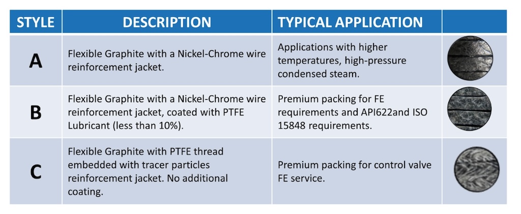
Using a proprietary friction test, three fugitive emission packing styles — A, B and C — were tested for their ability to withstand the demands of the applications they were used in. The distinct composition of each packing material is described in Figure 1.

The friction test uses a NPS 2 class 300 control valve as a test rig with load-sensing studs can accurately determine the packing stress and thermocouples in both the valve body and the stuffing box. The test involves progressively applying varying packing stresses in stages (Figure 3) and measuring the friction generated during a full mechanical cycle of the control valve for each stage. The full test procedure consists of the following steps:
-
Pre-load (1 MPa) is applied individually to each ring to accommodate the packing.
-
A total of 5 rings are installed in the stuffing box.
-
The test load to reach a target packing stress is applied.
-
Packing is allowed to dwell for 3 minutes.
-
The same test load is re-applied.
-
Valve performs one complete mechanical cycle.
-
The test evolves to the next packing stress stage and steps 3-7 are executed again.

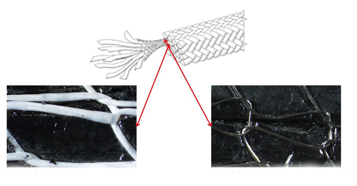
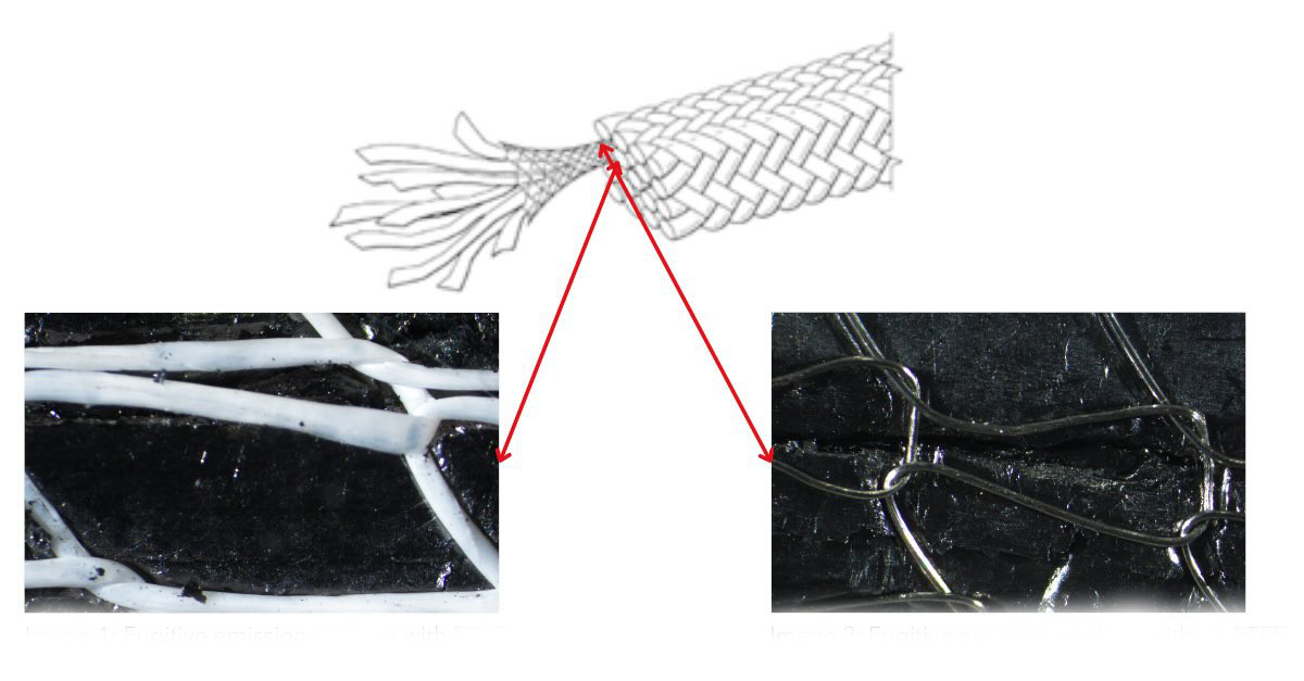
Style A is a flexible graphite packing style with a Nickel-Chrome reinforcement jacket. Style B is similar but includes a special PTFE coating (less than 10% by mass). Style C replaces the Nickel-Chrome reinforcement jacket with a PTFE thread reinforcement jacket and has no coating.
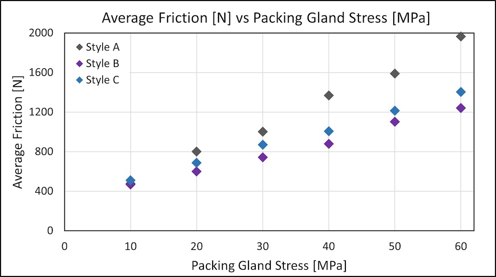
The friction test was conducted at room temperature and a high temperature (260° C) for each of the three packing styles. The results provide insights into the differences between these styles and the relationship between PTFE and friction. Figure 4 illustrates the average friction results for each packing style under increasing packing stresses at room temperature, while Figure 5 shows the corresponding results at an elevated temperature of 260 °C.
At room temperature, Style A generated 40% more friction at the highest stress level when compared to the other two styles. This discrepancy became even more pronounced at high temperatures, with Style A generating almost double the friction of Styles B and C.
Styles B and C, on the other hand, had similar friction results for both room temperature and elevated temperature friction tests. This is noteworthy because style C does not have PTFE coating. Instead, the thread of the reinforcement jacket in style C is PTFE, which reduces friction.

The role of leakage
While the friction test offered valuable insights into the friction behavior of various packing styles, it did not address their actual sealability or FE performance. To evaluate these factors, each packing style underwent an ISO 15848-1 control valve test procedure using the same control valve as in the friction test; it provided a comprehensive comparison of their leakage control capabilities.
The test procedure follows the standardized procedure, with the following key parameters:
-
Thermal cycles: 2 cycles (Room Temperature to 260 °C)
-
Mechanical cycles: 20,000
-
Stem stroke: 50% ± 10%
-
Stem speed: 2 mm/sec
-
Media pressure: 40 bar (Methane)
-
Packing stress: 60 MPa (5 rings)
-
Leakage measurement: Method 21.
Leakage measurements are then classified into tightness classes according to ISO 15848-1, as summarized in Figure 6.

Test results for styles A, B and C
The test results are depicted in Figures 7, 8 and 9. In each figure, the yellow line represents the internal pressure (methane), the blue line represents the packing gland stress (measured via load-sensing studs) and the orange line displays the stuffing box’s temperature. These figures collectively illustrate the gland stress, pressure and packing temperature throughout the test. Annotations mark different test steps. Finally, the friction and leakage are shown by the test step and the number of mechanical cycles.


For Style A, the minimum packing stress (gland stress) was 22 MPa (at test step 9), and the maximum leakage reached 142 ppmv (also at step 9). The average leakage throughout the test was 38 ppmv. The leakage corresponds to the tightness class CM, and overall performance class ISO FE CM – CC1 – SSA 0 – t200° C class.


For Style B, the minimum packing stress was 31 MPa (at step 9), and the maximum leakage was 2 ppmv (also at step 9). The average leakage recorded during the test was 0.62 ppmv. This leakage corresponds to the tightness class AM, and overall performance class ISO FE AM–CC1–SSA 0–t200 °C class.
These results reveal two key observations. First, the PTFE coating on Style B significantly reduced overall packing relaxation, with the final packing stress settling at 31 MPa. Second, it reduced the maximum leakage from over 100 ppmv to less than 10 ppmv, placing the packing in the best tightness class in the standard, AM.


Style C had a minimum packing stress of 32 MPa (also at step 9), and its maximum leakage was 4.2 ppmv (at step 3). The average leakage was 0.56 ppmv, achieving it the same leakage and performance class as Style B: ISO FE AM – CC1 – SSA 0 – t200 °C.
Style C showed even less packing relaxation than Style B while maintaining excellent sealability, with a maximum leakage well below 10 ppmv. Similarly, achieving the best thickness class in the standard.
Conclusive findings
Style A, a flexible graphite packing style reinforced with a Nickel-Chrome jacket, showed significantly higher friction compared to styles B and C, both at room and elevated temperatures. It also showed greater relaxation and leakage during ISO 15848-1 testing, with leakage rates exceeding 100 ppmv and achieving only a ‘CM’ performance class.
Style B, which features a PTFE coating, and style C, which substitutes the Nickel-Chrome jacket with a PTFE thread jacket, demonstrated reduced friction and improved leakage performance. They maintained overall leakage rates below 10 ppmv and earned an “AM” performance class. This indicates both styles are suitable for FE service.
For applications that cannot contain Nickel-Chrome wire jackets, and must reduce FE, style C stands out. It achieved the requirements with a PTFE reinforcement jacket and no additional coating. This is particularly important for control valve applications, where limited actuation force makes packing friction a critical factor. Additionally, Style C poses no risk of mechanically scratching the stem, even if it is made of a relatively soft metal. One can therefore conclude using PTFE is necessary in FE applications.
