Many industrial applications require multiple drives mechanically coupled to a common load. This is why drive/motor load sharing is so important.
Learning Objectives
- Determine the best options for drive/motor load sharing when multiple drives must be coupled to a common load.
- Learn about motor protection when load sharing must be implemented.
- Discover the importance of appropriate motor sizing when load sharing is necessary.
Drive/motor load sharing insights
- Multiple motors are sometimes needed to drive a common load.
- Controls that allow motors to share a load range from simple to sophisticated.
Many industrial applications require multiple drives mechanically coupled to a common load. When specifying a new or retrofit multiple-drive system, you are confronted with several choices of motor and drive technologies. In addition, you may have to evaluate an existing inventory of motors and drive components for possible reuse.
Load sharing concepts
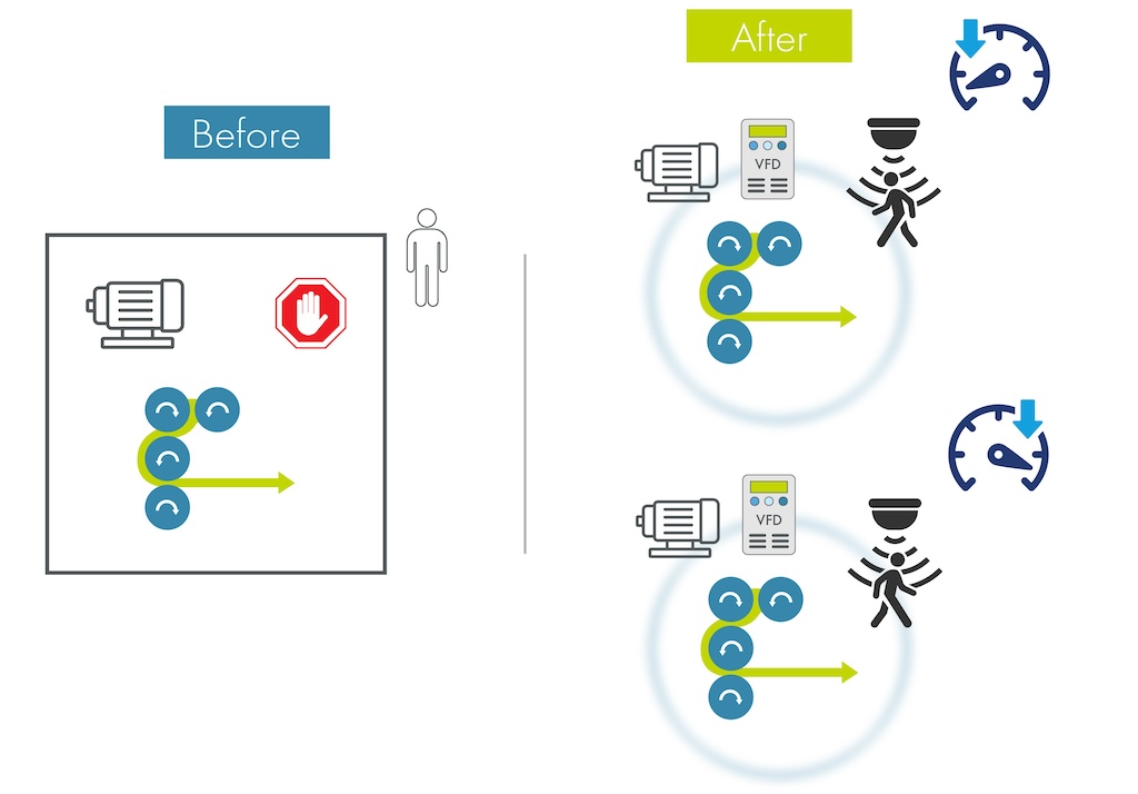
Consider the example of a conveyor system carrying parts and assemblies to various locations throughout a manufacturing facility. As each location performs a particular function, such as machining, painting, drying, loading, and unloading, the system must respond to the resulting load transients and speed deviations by distributing the load among the drives.
Take for example an overhead chain conveyor system utilizing two, 5-horsepower motors to move engine blocks. When a block is placed on the conveyor in the loading area, drive motor A sees the load first and slows down. Slower chain movement near A causes an increase in chain tension between A and B, forcing B to produce more torque. As a result, B slows down to speed-match A. As both motors speed-match, they also share the load. The transient is absorbed by both motors and the system returns to a state of equilibrium.
This load sharing occurs only under very specific circumstances. Optimum design requires physically locating the drives so each is pulling its share of the load. Several loading conditions, including inclines and declines, complicate the process of locating the drives. This example is based on ideal system conditions. Additional circuitry is almost always necessary to ensure true electrical and mechanical load sharing. Both ac and dc drive systems are capable of load sharing, but they each employ very different control strategies.
An older method for load sharing
In the past, a common method for achieving load sharing on conveyor systems was to take advantage of the forgiveness inherent in eddy current drives. This approach requires only a single controller powering two or more magnetic slip clutches. The controller is usually a small single-phase SCR power bridge that provides regulated current for the clutches. The clutch currents can be trimmed through the use of high wattage field trim rheostats, permitting individual clutch control. As a result, torque gain for each clutch can be trimmed until mechanical load sharing is achieved.
The clear advantage of this configuration is simplicity. The magnetic coupling between the clutch output and motor is forgiving and dampens sharp load transients. These characteristics made eddy current drives popular with manufacturers of material handling equipment.
Speed feedback is usually provided by an ac generator (24 to 36 V/1000 rpm), resulting in poor speed regulation at the low end. Although manufacturers publish a 34:1 speed range, these drives have trouble providing usable torque at speeds lower than 200 rpm. Additionally, controllers often utilize analog electronics which are subject to drift with temperature change.
The popularity of eddy current products has diminished and will continue to do so. Not only are eddy current drives inefficient, they are expensive to buy and difficult to repair. Since the demand for eddy current products is decreasing, manufacturers are reluctant to allocate development resources for product enhancements. In general, eddy current installations should be targeted for replacement.
Using ac drives
AC drives have become extremely reliable and are rapidly becoming the number one choice of industry. Take for example a two-motor conveyor system using commonly available variable frequency drives. Most ac drive products are microprocessor-based and tend to offer more performance adjustments than needed. Dynamic responsiveness, often a bragging point, is rarely a critical issue. In fact, stiff speed regulation makes load sharing impossible.
For most industrial material handling applications, an open loop volts/Hz-type ac drive is appropriate. The term volts/Hz refers to a control strategy based on a proportional relationship between applied stator voltage and frequency. An induction motor produces constant torque as long as a fixed relationship is maintained between voltage and frequency.
Variable frequency voltage supplied to the motor stator by the vast majority of ac drives is a pulse width modulated (PWM) wave form, which determines the motor field strength. By making adjustments to the volts/Hz profile, each motor can be made to pull its share of the load without overloading.
Generally, so many adjustment parameters are available that custom volts/Hz profiles are unnecessary. Instead, torque compensation gain dynamically controls voltage boost to the motor. This boost is most effective at starting, when one conveyor section normally carries a greater percentage of the load.
Slip compensation is another adjustment that provides trim to the stator frequency based on the current. Slip compensation controls a slight offset to the volts/Hz profile, modifying the motor’s torque output, and is most effective at higher speeds. In the event these adjustments produce insufficient results, modifying the volts/Hz profile will have a more profound influence on motor torque. Again, each ac drive can be fine tuned to accommodate virtually any load characteristic.
Cost savings, but at a disadvantage
A one-drive, multiple-motor configuration will also load share. Consider a single, large, ac drive with two smaller motors. Although the cost savings for this configuration are significant, there are several disadvantages. None of the adjustments that enhance load sharing are of any significance since all motors receive the same output. Load sharing is now dependent on the inherent slip/torque characteristics of each induction motor.
Therefore, accurate motor sizing becomes critical. A linear relationship exists between torque and slip over a portion of the curve. Upon receiving a load transient, each motor follows this linear region until they load share. Therefore, emphasis should be placed on using equal size motors, and they should all be of the same design type. An example is National Electrical Manufacturers Association (NEMA) B.
Motor protection presents another problem, since it is impossible for an oversized ac drive to protect smaller ac motors. Individual overload relays can be used to provide protection, along with thermostats embedded within the frames of the motors. In general, applications involving multiple ac motors with a single ac drive require much consideration regarding both performance and protection.
Using dc drives
The simplest and most effective load sharing approach uses dc drives. This method is clearly a contender if you are contemplating reworking/ retrofitting an existing system having an installed base of dc motors. Take for example a conveyor system using multiple dc motors. Many industries have used this configuration ever since the dc drive became a commercially available product.
Torque linearity and efficiency are the real advantages offered by dc drive systems. When a single drive is used to control two or more motors, all fields are usually connected in parallel to a full-wave bridge rectifier. The field winding controls a dc motor’s torque gain, or the relationship between armature current and output torque. A trim rheostat is provided for each motor’s field winding.
Trim rheostats in the armature circuits provide voltage drop compensation, primarily for variations in armature circuit wiring. An ammeter, usually a simple analog type, in the armature circuit provides an indication of load current. The goal is to get both motor armature currents to match, indicating successful load sharing. The dc system provides better speed regulation than the ac, because it utilizes a tachometer or encoder for speed feedback. Only one motor provides speed feedback, while the other receives identical armature voltage.
The dc system is considered the easiest for achieving a balanced load condition. Since a dc motor has two separate windings for control, sizing the trim adjustments for the armature and field circuits is the only real challenge. A rule of thumb is that the field and armature trim rheostats should be about equal to the field and armature resistances.
This system remains attractive simply because of the large installed base. Many older metal fabricating and automotive plants have existing dc motors they would prefer to use. Also, installation and startup tend to be trouble free for this method.
Sophisticated load-sharing techniques
Process systems often require multiple drives that must work together with great precision. Here, load sharing is accomplished without any form of external trim adjustment. A common control method used is the torque regulated speed follower (TRSF). Many ac and dc drive manufacturers have employed this control strategy.
TRSF provides speed follower control in combination with current (torque) control. Drive torque is regulated under normally loaded conditions, and automatic speed follower control acts in the event of a sudden drop in output torque. Within the control algorithm, the torque reference is compared with the actual torque to produce a speed trim error. As a result, when the actual torque is less than the set torque reference, the resulting error speeds up the drive, increasing output torque. If the opposite is true, the drive slows down, decreasing output torque.
Motor torque is well regulated through the use of this speed variable. Of course, this design requires that each motor have its own drive. Originally, torque references were exchanged between drives through an analog 0-to-10-V command. However, with the increasing number of digital ac/dc drive products, these variables are now passed over high-speed communication networks.
Appropriate networks
A local area network (LAN) offers the necessary speed to pass time-critical control variables such as torque or speed references without affecting stability. Information is transmitted as a collection of logic and numeric data. Data packets or tokens define message content and are transmitted in either a directed or broadcast format. Each node has a predetermined period of time to accept and process each token. The TRSF algorithm runs well within a LAN environment because speed and torque variables are rapidly passed across the network.
The tradeoff for the high performance delivered by ac/dc drive products with LAN communication hardware and software is that costs are relatively high. Use of these products is justified when it is necessary that speed and torque be maintained between machine sections with great precision. Otherwise, on simple, less critical mechanical systems, one of the other methods discussed here work well within most industrial performance specifications.