In making the right choice, consider operational costs and project complexity.
In materials handling and assembly there are many ways to move an item from one location to another. Conveyors can only move objects in a fixed path, limiting their use in many manufacturing applications. When more precision is required than a conveyor can deliver, such as when the part orientation or alignment needs to be changed, a pick-and-place system is often used. Pick-and-place technology is also typically used for packaging applications in which items are placed in containers or stacked.
The most common pick-and-place systems employ either pneumatics or electromechanical systems (See Figure 1), with hybrid electric-pneumatic systems also an option in some applications. The question then becomes what system is the best for each application, taking into consideration multiple factors including cost, complexity, performance, and maintenance.
The amount of movement(s) that must be performed, the required accuracy of the placement, the weight of the objects to be lifted, the shape of the parts, the distance they must travel, and other such considerations will determine the system best suited for the application.
In general, jobs with complicated movements requiring a high level of accuracy need more expensive electromechanical pick-and-place systems. If the application has a fixed travel path and doesn’t need repositioning or multiple positioning, a pneumatic pick-and-place system is often the best choice.
Hybrid systems use electrical components at the front end, and a pneumatic end effector to handle the part or object. These systems are more expensive than pneumatic solutions and less costly than electromechanical systems, and can be the best option for some applications as they combine the economy of pneumatics with the speed and accuracy of electromechanical systems.
This article will cover the basic design considerations as well as the best commissioning techniques for simple pick-and-place pneumatic devices.
When pneumatics are better
Although initial cost is often the driving force for using pneumatic pick-and-place systems instead of electromechanical solutions, it’s not the only reason (See Table 1). Pneumatic devices have a greater force density than many electromechanical solutions, which enables them to be a smaller and lighter, lowering space needs and energy costs. They can be also installed without requiring complex software programming of controllers, as their operation is simpler with a single path of travel.
In applications with contaminates, such as possible splashes, electromechanical systems pose more danger and are more likely to fail. Furthermore, electromechanical pick-and-place systems for these types of applications usually require specialized certifications and have a relatively small pool of vendors, thus making them quite expensive.
Pneumatic systems are not only safer in wet or corrosive environments, they can also withstand numerous cleanings. The pneumatic devices can be mounted close to the process while the associated electronics are housed in a cabinet well away from possible damage, simplifying installation and maintenance. Moreover, since controls for a pneumatic system are typically smaller than servo drives, internal space requirements in the control cabinet are reduced
A pneumatic system is simpler than an electromechanical system in terms of design, programming, installation, and maintenance—and good engineering practice dictates the use of the simplest solution that meets application requirements.
Build or buy?
When the decision is made to implement a pneumatic system, the next choice is to buy an off-the-shelf system or to build one using cylinders, valves, and end effectors. A preconfigured system will be in operation faster as it comes with all components pre-assembled and tested. Designing and building a custom system will take more time up front, will cost less in terms of purchased parts, and will result in an optimal fit for the application.
Custom pneumatic pick-and-place systems can be built in a variety of configurations using standard components, which are assembled to produce different linear and rotary motion actions. A basic system can be built using primarily off-the-shelf components at a very reasonable cost. Nevertheless, designing a pick-and-place system requires a certain amount of engineering skill.
Pneumatic pick-and-place systems rely on cylinders that take the energy of compressed air to create mechanical movement in either a linear or rotary direction. Round body cylinders are the least expensive option, but they require mechanical guides that usually must be custom machined for the particular application. As such, they may be the best choice for a company that can perform machining in-house.
For those without in-house machining capabilities, guided-rod extruded-body cylinders are a good choice even though they can be up to five times as expensive as their round body counterparts.
Either of these cylinder types can be combined with other components to perform multiple steps.
Rotary actuators are used with cylinders to perform non-linear, twisting movements; they can flip, tilt, or turn a part or an object (See Figure 2). For example, one cylinder is used for the vertical axis with a rotary actuator on top of one end of the vertical axis, while the other end has a gripper. This enables the actuator to move parts in an arc motion, instead of moving the object up and across in separate movements. It should be noted these actuators typically don’t rotate more than 270 degrees.
While readily available pneumatic cylinders are generally limited to about 2500 lbs of available thrust, a good engineer can combine multiple cylinders and supporting structure to build a very powerful pick-and-place system.
Cylinders and other components of a pneumatic pick-and-place system come in a wide range of materials: nickel-plated brass, aluminum, steel, and stainless steel. Users can select the appropriate material depending on loads, environmental conditions, and cost constraints.
Stroke length considerations
The stroke length determines how far the pneumatic device can move. Single-acting cylinders use the pressure of the compressed air to create a driving force in one direction, with the cylinder returning to the starting position via a spring.
These cylinders have limited extension resulting from the space needed for the compressed spring. A second consideration in using single-acting cylinders is that some of the force produced by the cylinder is lost when it pushes against the spring. Single-acting cylinders are best suited for applications that only need approximately 6 in. (150 mm) of stroke length or less.
Double-acting cylinders use the force of compressed air for both the extending and retracting strokes, with two ports to bring in air, one for the outstroke and one for the instroke. Stroke length for this design is generally available up to 24 in. (600 mm) in most popular bore sizes. For travel distances longer than 24 in., there are a number of different rodless cylinder designs that work very well in pick-and-place systems.
Direction and speed control concerns
While pneumatic pick-and-place doesn’t offer the speed control and wide range of motion found with electromechanical systems, it can deliver an often acceptable level of control by using valves to control direction and speed.
Flow control or needle valves are used to control the speed of the pneumatic pick-and-place device by regulating the airflow to the actuator. Overall system sizing of valves, tubing, and actuators will have an effect on achievable speed range, and greater care should be used if speed is critical. Solenoid valves switch the air from one side to another for direction control, and advances over the last decade or so have greatly eased implementation. In the past, each electric solenoid had to be individually wired to a controller relay output. However, today’s pneumatic systems use small, low-power solenoid valves that connect directly to the standard discrete outputs of a controller.
Valve banks are also available that use several popular automation communication protocols for easy integration. These valve banks are mounted locally to the pneumatic system and are connected to the controller via a digital data link transmitted over a single cable.
Valves and cylinders used to be high-maintenance items, but newer materials and lubricants simplify the installation and maintenance of pneumatic systems. Many valves and actuators are now permanently lubricated at the factory. Kink-resistant flexible tubing and push-to-connect fittings also ease installation and repairs.
Position sensor specifics
Reliable solid-state position sensors are used to close the loop with the main controller. For pneumatic systems, discrete sensors send electrical signals to the controller to report the piston’s position. In today’s high-speed production systems, it’s often important to identify end-of-stroke position feedback from cylinders since air system pressure and flow fluctuations may cause changes in stroke speed.
There are a variety of sensors to meet different requirements. One kind of sensor uses external electromechanical limit switches or inductive proximity switches to detect metal flags on the moving parts of the machine. However, installation can be complicated, requiring brackets and hardware that also increase the size of system.
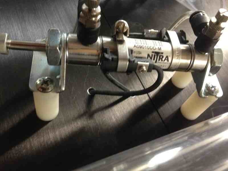
Using magnetically actuated switches or sensors mounted on the sides of the cylinder or in a slot on the cylinder body is a more common approach. The sensors detect the magnetic field of an internal magnet on the moving piston through the wall of the pneumatic cylinder. The sensors typically detect end-of-stroke in either direction. Multiple sensors can be used to detect several discrete positions along the length of a cylinder as well (See Figure 3).
Grippers and vacuum device deployment
The end effector that picks up the object can be pneumatic grippers or vacuum suction cups (See Figure 4), both of which are usually lighter, smaller, and less expensive than electric grippers.
Pneumatic grippers work well for applications requiring high speeds or a high gripping force. While they don’t offer the force and positioning attributes of electric grippers, pneumatic grippers can be adjusted by using a control valve or an analog proportional pressure valve to change pressure and thus gripping force.
The initial cost of suction cups is low, and they come in a variety of sizes. Suction cups are a good choice for delicate products, such as food and glass, and for flat objects like paper and sheets of metal. While they work for some high-intensity applications, the operational cost of the required vacuum generators may be prohibitive for systems with just a few cups.
For inexperienced users, suction cups can be tricky to implement. Selecting the right size and amount of suction is often more of an art than a science, and determining the size and suction of the cups is often an exercise in trial and error unless considerable experience has been gained in similar applications.
Development and testing tips
When building a pneumatic pick-and-place system, dry cycle without parts or objects at very low speeds to verify clearances and the sequence of operations. If flow control valves are being used to regulate cylinder speed, use these devices to control velocities. If not, adding time delays or temporary stops between sequence operations in the main controller is often a good method to control the speed.
Without adding the product, the speed of the sequence should slowly be ramped up to the maximum speed for the operation. The speed should then be reduced substantially and the parts or objects to be handled should be added. Once again, the cycle times should be slowly increased up to the desired operational speed.
Reducing total cost of ownership
One of the complaints about pneumatic pick-and-place systems is relatively high operating costs compared to electromechanical systems because they use compressed air. Most pick-and-place systems will operate in settings where compressed air is already being used for other purposes, and several steps can be taken to mitigate air usage.
Correct sizing of components will reduce air consumption, and online calculators and configuration tools can be used to guide a designer. Using only the minimum amount of required pressure can lower air consumption by up to 25%. Pressure regulation of specific steps, such as lower pressure for the return stroke of an actuator, can also lower air consumption while maintaining optimal performance.
Another way to reduce costs is by mounting the pneumatic control components near the point of operation to minimize air line lengths. Locating the valving close to the actuators and using appropriate cylinder and valve combinations can reduce the required air volume by up to 35%.
In addition, modern components reduce leakage, and improved lubricants can operate across a wider temperature range. These measures extend the life of actuators and valves, reducing the costs of maintenance and replacement.
Misconceptions and outdated ideas about pneumatics can needlessly drive up the cost of pick-and-place by relegating users to higher priced electromechanical systems. When just two positions per axis of motion are required, and when very high speed and extreme precision aren’t required, pneumatic pick-and-place systems will usually be a simpler and less expensive option. Digital networks also make it easy to integrate pneumatics into sophisticated automation systems, reducing installation and maintenance costs.
While it has been used for decades, pneumatic pick-and-place has benefited from technological advances, making these well-tested systems a valuable option for many applications.
Key points:
- In trying to keep it simple, a pneumatic system is simpler than an electromechanical system in terms of design, programming, installation, and maintenance.
- Correct sizing of components will reduce air consumption. Using only the minimum amount of requires pressure can lower air consumption by up to 25%.
- While pneumatic cylinders are generally limited to about 2500 lbs of available thrust, engineering can combine multiple cylinders to build a more powerful system.
