Knowing common motor starting methods and the differences between them ensures the optimal selection for any given process
Learning Objectives
- Understand the purpose of motor starters.
- Learn about the common types of motor starters.
- Review the advantages and disadvantages of different motor starters.
Motor starter insights
- Protecting the motor from the inrush current requires plant engineers to understand when motor starters can benefit a system.
- This article will provide an overview of the common types of motor starting methods for low-voltage induction motors along with pros and cons for each starting method.
Induction motors convert electrical energy into mechanical energy (i.e., motion). In the process of conversion, the electrical supply connects to the motor stator, producing a rotating magnetic field that rotates the rotor and starts the motor. When the motor starts, it draws a very large starting current.
This starting current, which is also known as the inrush current, is typically five to eight times higher than the rated current of the motor. The high inrush current can easily damage or burn the windings of the motor and cause a huge dip in the supply voltage, which can damage other loads connected to the same power supply. As such, it is important to protect the motor from the inrush current by providing motor starters or drives.
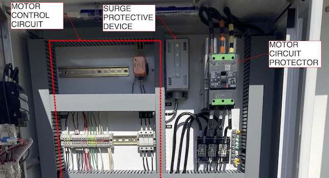
An essential component for any motor, whether an exhaust fan, blower or compressor, is the motor starter. To start and run motors, there are several options available, including across-the-line starters with a contactor, reduced-voltage with autotransformer (RVAT) or reduced-voltage soft starters (RVSS) with solid-state control and variable frequency drives (VFD). Each method has its own advantages and disadvantages regarding cost, size and capabilities.
Across-the-line (full voltage)
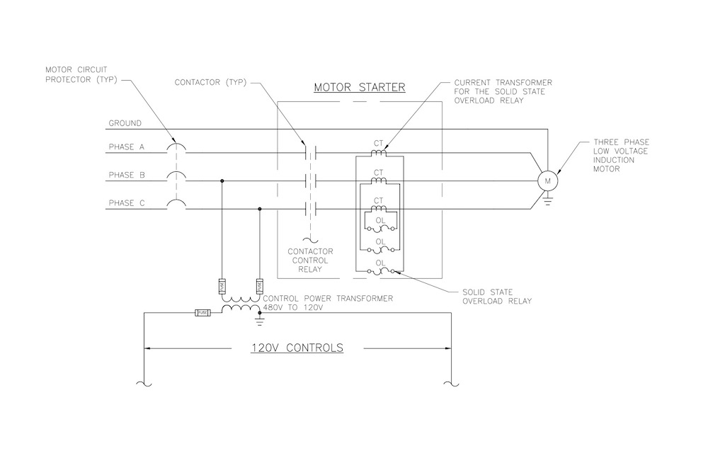
One of the most basic motor starting methods is an across-the-line motor starter, which is also known as full-voltage or direct-online. An across-the-line motor starter typically includes three components: the contactor, the motor circuit protector and the overload relay. Figure 1 details a generic wiring diagram of an across-the-line motor starter.
Contactors are normally open contacts that close the circuit when the contactor coil is energized. The contactor coil is typically connected to a control relay in the 120-volt control logic such that the motor can turn on/off depending on application.
For example, if the water level in a pumping well is high, the submersible motor needs to turn on to pump the water to another location. Or if the water level is low, the motor needs to turn off to prevent dry running, which will cause damage to the motor.
Overload relays protect the motor from excessive heat caused by overloading or stalling situations. An overload relay, either thermal or electrical, will monitor the heat or current flowing through the circuit. If the heat or current is above a limit over a certain period, the overload relay will trip, which will operate an auxiliary contact that interrupts power to the contactor coil and de-energize the motor. The motor circuit protector shown in Figure 1 is an overcurrent protective device (OCPD) that provides protection for the motor circuit. This OCPD can be a circuit breaker-type or fuse.
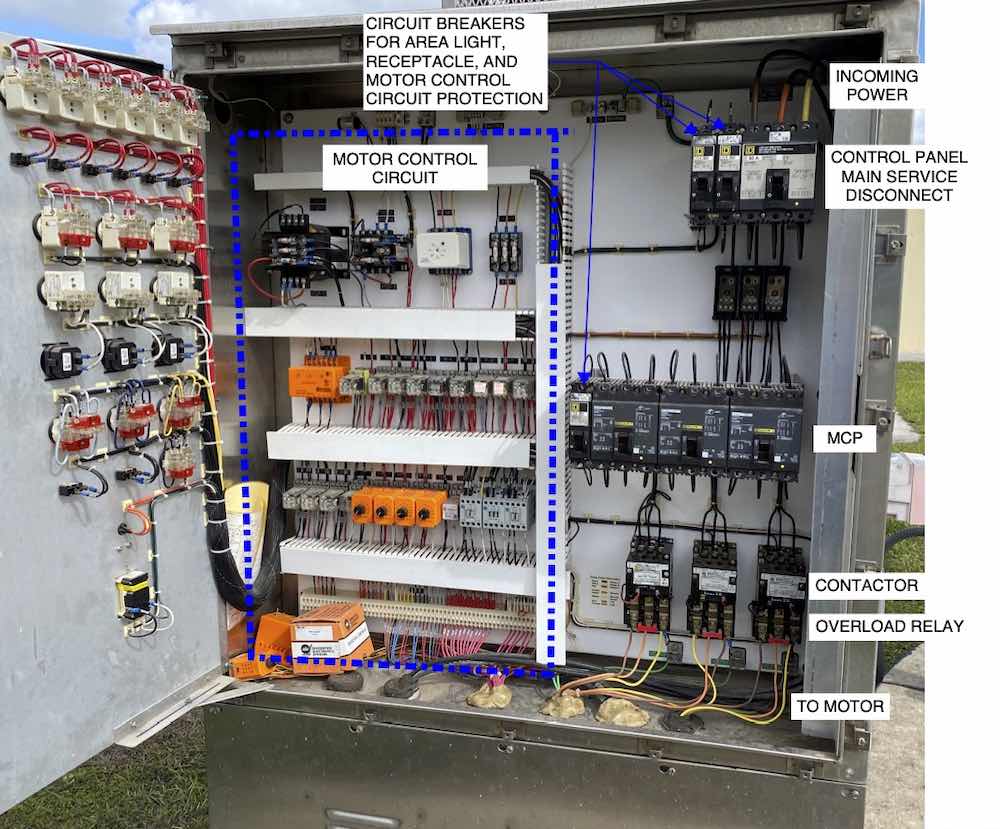
Figure 2 shows a National Electrical Manufacturers Association (NEMA) size 1 motor starter in a control panel for three pumps (triplex) in a wastewater lift station.
As shown in Figure 1, the motor starter is connected directly to the power supply, meaning full voltage, current and torque are applied instantaneously when starting the motor. Due to this, the motor accelerates to full speed quickly and will also have a high inrush current of short duration. The current reduces as the motor speeds up and when the motor is at full speed, the current will be at the rated motor current.
Because of their simplicity, across-the-line starters do not create switching that causes harmonics like VFDs. The motor will run constantly and consistently at 0% or 100% speed with an across-the-line starter, which is not ideal for applications where speed control is necessary (e.g., odor control blowers, etc.).
When stopping the motor, the power is instantly cut from the motor. The motor then spins down on its own, which can lead to hard or fast stops. For bigger motors, this can damage the motor windings due to the heat.
Due to motor heating, voltage drop, large current demand and strain on the other connected electrical equipment, across-the-line starting is not recommended for larger motors. The inrush current will be largest with this starting method, which for a large motor can create a need for an oversized generator or power system supply. However, compared to other motor starting methods, the full voltage motor starter can be the cheapest and most compact option for smaller motors.
Soft starters
Soft starters are devices used to temporarily reduce the torque and current provided to an alternating current (ac) electrical motor during startup. These devices are meant to reduce mechanical stress on the motor, electrical distribution equipment and any generator systems supplying power. Soft starters can come in the form of mechanical or electrical devices. Two common electrical devices used for soft starting are RVSS and RVAT soft starters.
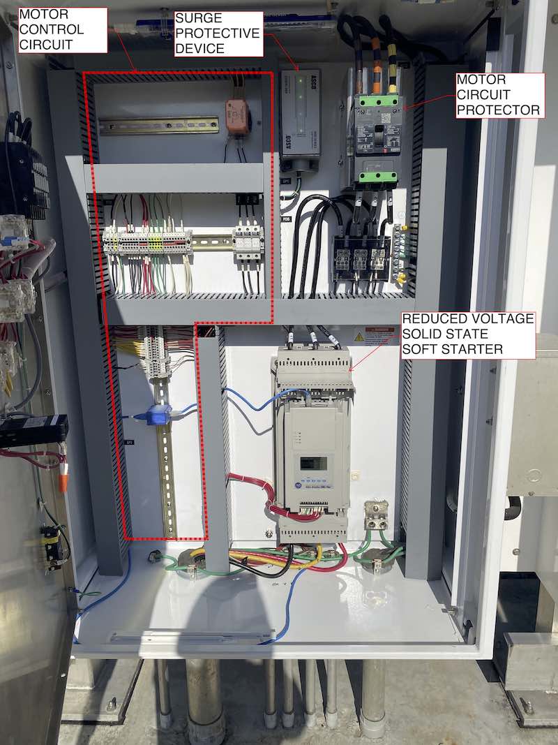
RVSS are a type of soft starter designed to control the starting voltage to provide smooth, controlled starting to a motor by reducing the motor torque. For stopping, the motor can also be gradually slowed down instead of having to hard stop. Figure 3 shows a picture of an RVSS in a control panel for a 75-horsepower submersible well pump.
The method of voltage control comes from silicon-controlled rectifiers, also known as thyristors, operated with a controller to set starting torque and current and slowly ramp a motor up to speed. Once a motor is at full speed, many modern RVSS will use internal bypass contactors to provide power to the motor. This is done to reduce the wear and tear on the starter, increasing its life span.
Some disadvantages of RVSS over full-voltage starters are the increased heat generation during startup, the increase amount of spaced required and the increased initial cost for the device.
RVAT are a type of soft starter that uses the secondary of an autotransformer to provide reduced voltage to a motor by using preset output taps. These taps are usually at 50%, 65% and 80%. During startup, the reduced voltage is used to get the motor spinning, until a set time or line current has been reached and then the motor bypasses the RVAT to operate at 100% voltage. During shutoff, there is no soft stopping and the motor is immediately disconnected just like a full-voltage starter.
Other disadvantages compared to RVSS are the increased footprint of this device, the increased weight of this device, increased heat generation from the transformer and limited control over starting speed because the limited number of output tap options. With all these disadvantages and the fact that RVAT soft starters are roughly the same cost, it is no surprise that RVSS are generally the preferred solution.
The only advantage RVAT has over RVSS is the simple and robust design that requires a limited number of parts.
Variable frequency drives
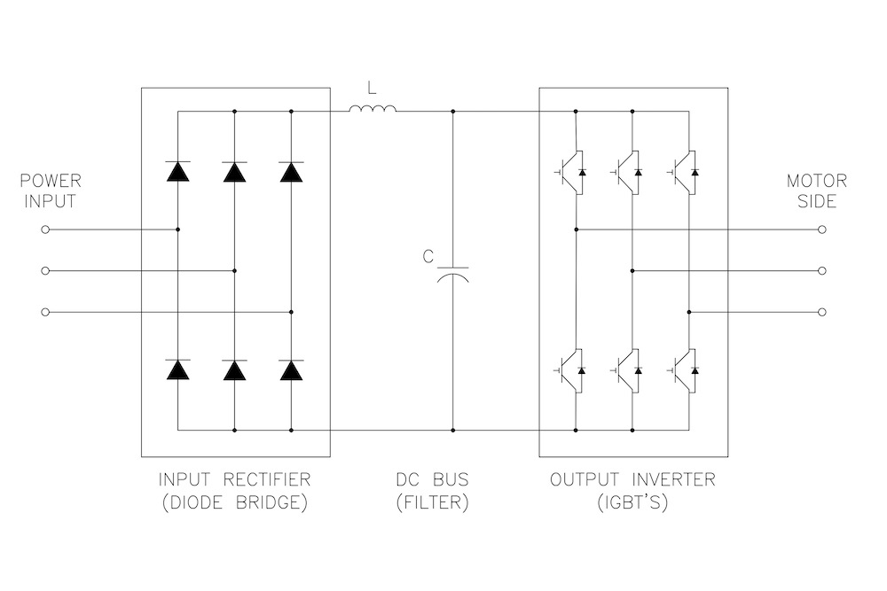
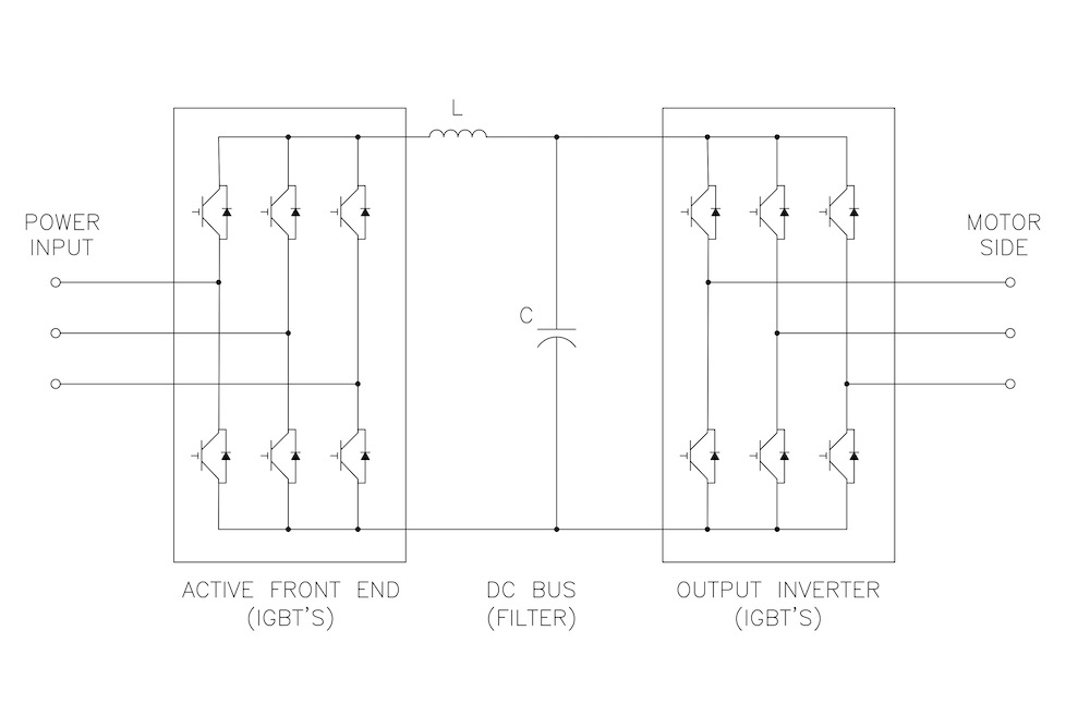
VFDs are a type of soft starter that are used to not only start and stop a motor slowly, but also to control the speed of ac motors. VFDs operate by converting input ac to direct current (dc) power, smoothing the dc power using an inductor capacitor filter and, finally, converting the dc power into a simulated, through pulse-width modulation, sine wave using an inverter consisting of insulated-gate bipolar transistors (IGBT).
The exact method of power conversion will depend on whether the VFD uses a pulse rectifier, such as 6-, 12- or 18-pulse, or an active front end drive. See Figure 4 for a 6-pulse wiring diagram and Figure 5 for an active front end wiring diagram.
Each type has its advantages and disadvantages, especially when dealing with the disadvantages associated with VFDs. Some disadvantages are harmonics, reflected waves, heat generation and increased initial cost.
Harmonics are a concern for the line-side of the VFD created by the rectifier and inverter and have various negative effects, such as causing capacitor banks to fail, burn out motor windings, trip circuit breakers and cause transformer overheating. Some VFDs produce more harmonics than others, for instance, a 6-pulse drive will produce more than an 18-pulse drive and an 18-pulse drive will produce more harmonics than an active front end drive.
However, a 6-pulse drive is the cheapest VFD, while an 18-pulse drive and active front end drive costs roughly the same. Note, even if a 6-pulse drive is selected, there are methods to reduce harmonics, such as in-line reactors or external harmonic correction units.
Reflected waves are a concern for the load-side of the VFD caused by the quick switching of IGBTs and can create overvoltages that damage cable insulation, motor windings and motor insulation. For this reason, it is important to consider inverter duty motors, which are made to handle larger voltage differentials. Another solution is to install either a load reactor, dv/dt filter or sine wave filter or locate the VFD close to the motor, as the reflected waves get worse with distance.
Heat generation comes from the many parts of the VFD required to convert the ac current to dc and from the switching of IGBTs to produce a simulated sine wave. While the switching frequency can be lowered to reduce heat generation, it is not always advisable because it can increase harmonics from the VFD and noise from the motor.
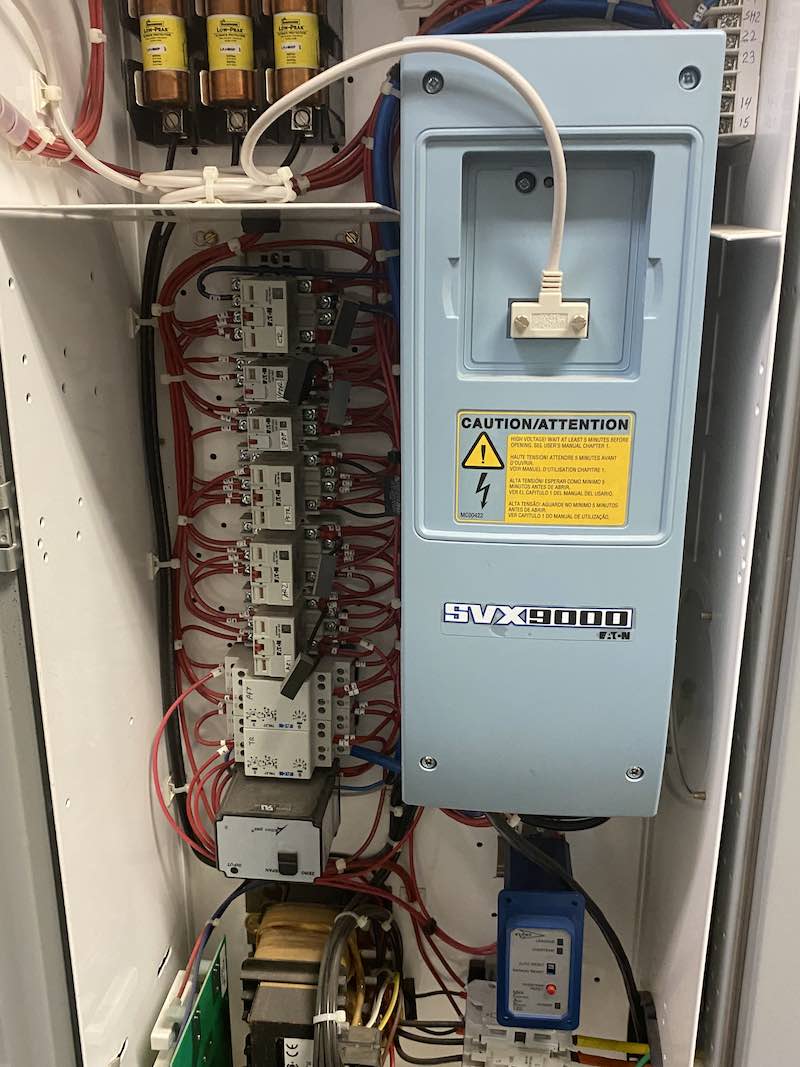
The best method of preventing overheating is to use heat sinks and fans to dissipate heat through vents in the VFD enclosure. Ideally, VFDs would be installed inside a climate-controlled electrical building or room, but many vendors do provide external VFDs with air conditioning units. See Figure 6 for a VFD internally installed into a motor control center.
The last disadvantage is an important one as VFDs cost more than a RVAT or RVSS option. However, the increased initial cost and other disadvantages do come with some great benefits and capabilities. Some of these benefits are improved power factor, speed control and reduced energy consumption.
Power factor improvement is caused by the dc bus capacitors within the VFD. The dc bus capacitors provide reactive current to the motor, which is required to induce the rotor’s magnetic field. This means the input supply current from the utility only needs to be realpower. This benefit can help avoid power factor penalties from the utility, reduce current on the distribution network and reduce demand charges from the utility.
Speed control is an ability that allows the motors speed to be controlled by varying the output voltage and current of the VFD to achieve the required torque and desired speed. This can be done using an open-loop control method or a closed loop control method based on the application required. In the open-loop system, the VFD is tuned to ensure accurate speed control, while the closed-loop system monitors the voltage and current of the motor to read the motor speed and adjusts accordingly.
Reduced energy consumption is a product of reducing the speed of a motor and therefore the motor load. This is often a major advantage and can provide large energy savings. The reason such large energy savings can be gained is because of the relation between speed and power consumption.
For instance, a 50% reduction in motor speed reduces power demand to 12.5% of the original power demand, 42% power demand for 75% motor speed and 73% power demand for 90% motor speed.
Conclusion
When it comes to choosing a motor starting method, there are many choices depending on the desired motor application and motor size. The across-the-line starting method may be preferred for smaller motors that do not require speed control. Soft starters become important considerations for larger motors to reduce inrush current but does not offer speed control.
VFDs are a great option for large motors and/or motors that require or benefit from speed control. However, they introduce harmonics to the electrical system, which may need to be mitigated. Choosing the ideal method can ensure an efficient and cost-effective system at any facility.
