System integrators face common challenges with incorporating original equipment manufacturers (OEM) equipment into automation projects, but there are some proven strategies to drive success.
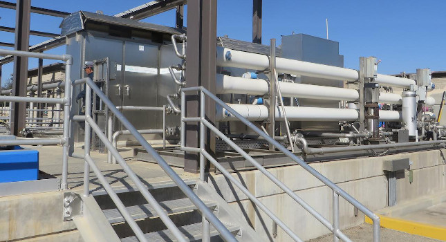
Using packaged equipment supplied by original equipment manufacturers (OEMs) is common in the water/wastewater industry (see Figure 1). OEM equipment, however, can create some specific challenges to the systems integrator (SI) responsible for the automation portion of a project, requiring a strategic approach to drive alignment with other components, systems and standards that may vary from the standard OEM offering. This article explores these challenges and describes strategies to drive success.
Three OEM system integration challenges
The challenges associated with OEM system integration can be categorized into three distinct areas:
- Contrasting standards in technology and configuration requirements
- New process technologies
- Project team coordination (see Figure 2).
Contrasting standards in technology and configuration requirements. There are many areas where OEM equipment may vary from the “unpackaged” equipment defined for a control system including programmable logic controllers (PLCs), local operator interface terminals (OITs), communication protocols and PLC and OIT software standards (see Figure 3).
Figure 2: Challenges for integrating OEM vendor equipment in water/wastewater projects can be categorized into these three areas. Courtesy: Tesco Controls Inc.[/caption]
Different communication protocols also must be aligned. There are several ways of doing this thanks to devices that have been developed to address this issue in modern control systems. These devices have evolved over time to allow legacy technology to be integrated with newer technology, and for equipment from different manufacturers to communicate within a single control system. The design needs to be analyzed to determine if the devices allowing the various OEM equipment PLCs to communicate with the rest of the system are appropriate for inclusion. Luckily, there is a solution that can be leveraged if there is an oversight identified in the design.
The PLC and HMI software standard variance can be very difficult to resolve, primarily because software standards are much more subjective compared to defined methods such as communication protocols.
Standards for the BOP system can come from several sources including the end user, plan and specification documents, a software platform manufacturer, programming workshops or additional contract team members (see Figure 4).
OEMs often produce standards they can offer as a cookie-cutter solution to keep costs low while still accommodating various industry installation requirements. The standards used by OEMs are often developed internally with their own group of software staff, with a focus on process function and other factors that do not and could not consider the overall BOP control systems.
These factors can cause misalignment between the OEM software standard and the standards defined for the BOP. The differences can range from minor like alarm nomenclature to major like color states opposite of BOP standards. Standards need to be evaluated and incorporated into the larger plan for the overall software design. This effort often falls on the SI given they are in a key position to help provide solutions using a collaborative partnership with consultants, design engineers, and end users.
New process technologies. There are many developing technologies and improvements. Understanding the application of these technologies, the process variables being monitored, the control strategies in use and the critical alarms for each system is imperative. This allows the SI to integrate OEM equipment effectively into a larger software model encompassing the entire BOP control system.
Getting a firm grasp on the specific process technology used by each OEM takes time and requires internal research often overlooked when the schedule for technical resources is developed. Decisions made regarding integration of the equipment into the BOP control system will be more effective if the integrator is able to understand the OEM’s process technology and communicate with the contract team and OEM representatives.
Project team coordination and communication. One of the more challenging aspects of projects with OEM packaged systems is how they are positioned within the contract team with respect to the SI (see Figure 5). The integrator is often a subcontractor or supplier to an electrical contractor, a general contractor or an end user. In most cases, however, the OEM vendors are subcontractors or suppliers to a general contractor. This can present a challenge in terms of establishing communication between the SI and the OEM, and the SI must therefore be the proactive party pushing to establish a line of communication.
This needs to happen early in the project as it can take time for communication channels to be established, and consequently for responses to requests for information to be provided. Some contract teams will allow the SI and the OEMs to communicate directly to work out technical details. However, this is not always the case, and the contract communication channels need to be respected.
This means additional diligence is required on the part of the SI to make clear requests for information and push for these items to move through a contract chain of stakeholders that may not see these requests and responses as the current critical path. The coordination, in any case, becomes challenging if there are design changes identified involving the OEM equipment and the equipment being supplied and configured by the SI.
The specifications sections related to the OEM vendor scope are often separate from requirements and standards for the SI regarding the integration of vendor equipment. This distinction is important because the information the SI needs from the OEM is more complex than the information the OEM needs from the SI.
The SI needs several pieces of information to complete its scope, which involves integrating some process information for the OEM equipment into the BOP control system. This includes the SCADA software platform for the BOP as well as data exchange between the OEMs’ PLCs and other control system PLCs that have critical control relationships with the OEM equipment. The SI must also stipulate what information is being requested from each OEM to satisfy plans and specs that require OEM equipment process data to be integrated into the BOP control system.
Integration strategies for success
To meet the challenges outlined above, a combination of these SI strategies must be employed: obtain OEM vendor information, define what components to integrate, determine aligning software standards and integrate technologies between OEM equipment and the BOP.
Obtain OEM vendor information. Success will vary depending on the OEM and the contract team structure, as well as the persistence of the SI. The information needed from the OEM vendor can vary, but there are some items that would be ideal in most circumstances. These include the PLC programs, or at a minimum the tags available for data exchange with other PLCs or integration with the BOP SCADA platform, as well as information about the OEM equipment including submittals to the contract team.
If there are OITs associated with the OEM equipment, these software programs should be received as well. Local OIT applications can shed light on the tags accessed within the OEM PLC to provide status, control and alarming. This information can also help resolve questions about the appropriate data to be integrated into the BOP SCADA software application.
Depending on the OEM, some of this information may not be provided at first because many OEMs consider these software applications to be part of their intellectual property (IP). Therefore, obtaining it may be challenging if the plans and specs or other contract documentation did not specify the vendor was required to provide this information. The end user, the general contractor and other parties on the contract team such as the consultant or the design engineer can be helpful to persuade the OEM to provide this information. In some cases, only a tag list is provided, which shows the variables defined for BOP SCADA platform integration or data exchange with other PLCs.
This list of variables, along with the plans and specs and any OEM submittals, are sometimes adequate for the SI to be successful, but this must be determined on a case-by-case basis. The best approach is to be clear and efficient with requests and to provide adequate justification for why the information is critical.
It is helpful when the SI is responsive to OEM requests. Showing courtesy and respect by being responsive can increase the chances of getting the same in return (see Figure 6). It is always worth asking for direct communication with the OEMs as it facilitates a faster resolution of issues.
Define what components to integrate. Several factors determine what information from the OEM equipment needs to be integrated into the BOP control system and at what levels this integration must take place. The two major areas where integration happens are at the process PLCs and at the BOP SCADA software application.
At the PLC level, an exchange of information between OEMs’ PLCs and other process area PLCs is often required. This is related to control relationships among the OEM vendor equipment that lies upstream, downstream or within a process train. Process variables including flows, pressures and analytical values — as well as, setpoints, interlocks, permissives, alarms and control commands — are all common components of a control relationship, and therefore require data exchange with OEM equipment.
Figure 7: Projects may allow a deviation for standard OEM equipment to not match the overall SCADA configuration, but sometimes the OEM programming must be modified to follow SCADA standards. Courtesy: Tesco Controls Inc.[/caption]
Operations personnel would typically need to acknowledge alarms at the BOP SCADA and at the local OIT to synchronize alarm statuses. Furthermore, discussions about the alarming strategy may lead to a request for all alarms to be integrated, which may also affect BOP SCADA licenses tied to tag count.
Determining what information is to be integrated at the early stages of a project is critical for sizing the BOP SCADA system and developing the technical software plan. As in the case of PLC data exchange, analysis is needed to ensure required information to be integrated is clear, accurate and appropriate.
Determine alignment of software standards. There are several areas where OEM software standards may not align with BOP control systems, including colors, graphic symbols, control methodologies, alarming, trending, navigation, overall graphic application structure and the PLC coding methodology. For example, if there are differences in the color standards between the OEM OIT interface and the SCADA system, a decision is required to determine how this information is displayed at the SCADA system, assuming the OEM will not change their color scheme. Many methods are possible for moving forward when this is the case, with selection of the best method dependent on what are identified as the most important factors.
A workshop environment is often a successful forum to work out the details of the SCADA software standards and other design components associated with the integration of OEM equipment. Through a workshop process or other collaboration within the contract team, it could be determined that it is most important for the colors to match. This could lead to a deviation on the SCADA system for this specific OEM process area to match the local display. It could also be determined that it is more important for the SCADA system standard to remain intact throughout the main SCADA application, and thus the OEM screens would need to be modified to match the overall system software standard (see Figure 7).
There will be many discussions necessary to develop an approach for each of the areas of variation. There is no right or wrong answer in this regard, as decisions have more to do with the needs of the end user and the intent of the design. As a result, they end up relying on the input of the various members of the contract team. All decisions must be documented so all parties understand what is being delivered as a final product.
Integrate technologies between OEM equipment and the BOP. When it is determined that data exchange is necessary between the OEMs’ PLCs and other plant PLCs or the BOP SCADA software, the next step is to validate whether methods are in place for allowing these components to communicate with one another. This involves a closer look at the network architecture, media, equipment, protocols, and I/O drivers used to gather data for the SCADA software platform.
If the design lacks the necessary provisions, additional components are required to facilitate communication between various devices. These could be networking components, PLC communication modules, protocol translation devices or gateways or software components — some or all of which may be needed so BOP SCADA software can access critical process data. Thorough analysis is beneficial for helping avoid issues in the later stages of the project where deadlines could be missed, or where critical data exchanges are not in place for startup and commissioning activities.
As with many other aspects of OEM integration, “earlier is better” represents the general idea when it comes to identifying potential issues and developing solutions.
Looking ahead
Integration of OEM equipment creates unique challenges for the SI responsible for incorporating these packaged systems into the overall BOP control system. Analysis of the initial design and focus on the issues associated with OEM equipment integration is necessary to develop an overall product aligned with the intent of the process control system design and meeting the needs of the project stakeholders and the end user. Communication is a critical component to successful integration and alignment, including documenting the collaborative decisions made by the contract team throughout the evolution of the project.
Tesco Controls Inc. is a certified member of the Control System Integrators Association (CSIA).