Compressed air systems use $1.5 billion a year in electricity, according to recent U.S. Department of Energy statistics. That amount equals 1% of all U.S. power generation or all of the annual electricity consumption of the state of Connecticut.
Compressed air systems use $1.5 billion a year in electricity, according to recent U.S. Department of Energy statistics. That amount equals 1% of all U.S. power generation or all of the annual electricity consumption of the state of Connecticut. According to some estimates, conservation measures could annually save industry $150 million and reduce greenhouse gas emissions by 700,000 tons, equivalent to removing 130,000 cars from the road.
Many plants are dealing with the waste by hiring professionals to conduct energy surveys of their compressed air systems. Key to helping in the performance of these surveys are state-of-the-art ultrasonic instruments.
In most cases, diagnosticians look at the pressures a plant needs to operate rather than at what pressures are actually used. They perform a pressure profile analyzing the differences in pressure between the compressor area and points of use in the plant to see how they compare. No one can stop all leaks, but anywhere there is a threaded fitting, the potential exists for leaks that should be controlled.
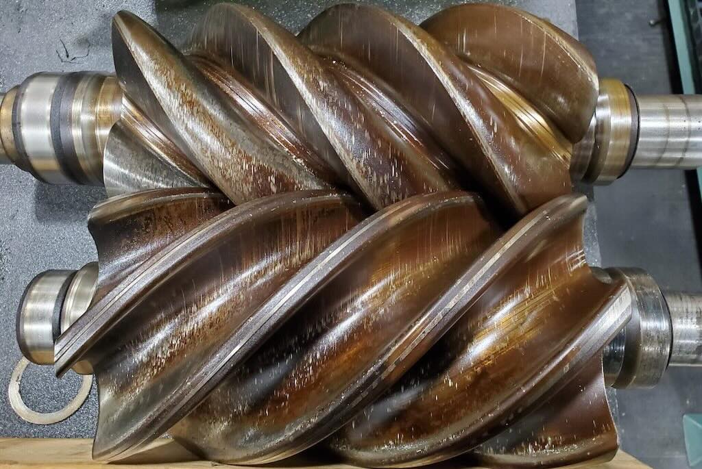
Typically, any plant using a lot of industrial “red hose” (the automotive type such as is used for a gas service station air pump), a hose barb that restricts airflow through the hose, and a stainless steel worm clamp that brings air from a fixed pipe to a machine has many potential leak points. A plant that uses hard piping, compression fittings, and a flexible full-flow hose has considerably less potential for leaks.
Detecting leaks with ultrasound
The best ways to contain leaks is to isolate areas or equipment that is not operating. When this action is not possible, ultrasonic instruments can be used to detect leaks even when a plant is fully operational or when there is significant background noise. The instrument picks up signals that are not audible to the human ear or in a noisy environment. An experienced inspector learns to distinguish normal sounds from warning sounds and can test, or shoot, through most typical plant noises to spot the source of a leak accurately.
The first step in a test is to inspect the hard piping. Any gas in a pressurized state (compressed air, nitrogen, or oxygen) expands into the atmosphere through the tiniest of holes. Instrumentation can pinpoint with accuracy the origin of the white noise produced by the expanding gas.
Aiming the ultrasonic instrument along the piping and through the points of use, the inspector listens through headphones for the sound of gas leaks. A rubber focusing probe is placed over the end of the scanning module to concentrate the area in which he is shooting. A sensitivity gauge on the instrument reacts as the inspector moves closer to a leak. When a leak is encountered, the sounds are distinctive.
The sensitivity dial on the device is typically set at an optimal level. An experienced inspector learns to adjust the dial according to the situation. To use the device, he points the instrument at the leak, typically from 18—20-in. away, and adjusts the dial until the gauge reaches 50%, or the center position. He then moves in the direction of the loudest sound level.
The same process applies whether the user is troubleshooting rejuvenators and cylinders or through walls and ceilings. Inspectors are looking for a gas expanding from a higher pressure back to atmosphere. Ultrasound travels in a straight line. Noise must escape somewhere. If an inspector targets a control panel on a wall and spots a leak through a panel perforation, he should be able to distinguish between an expanding gas present by design and one resulting from a leak from a loose fitting.
Most leaks occur where piping is exposed. About 99% are found at connection points such as where hard piping is joined to a machine with hoses or fittings. Occasionally, a leaking pipe is found in a ceiling, but usually only in exposed situations.
Hard piping tends to seal itself. Contaminants such as oil, water, and moisture coming through the pipe tend to seal small leaks over time. Connections made with improper pipe dope or without any type of silicone or Teflon tape are often points of potential leaks.
Quantify losses and savings
Surveys reveal about a quarter of all compressed air is wasted through leaks. This average can range from a low of 16% to as high as 60% in very similar plants. The difference is generally a reflection of a plant’s predictive maintenance processes.
Once a plant determines the cost of its compressed air (determined on the basis of brake horsepower needed to run the compressors times the power cost per brake horsepower), it can calculate the “per cfm” cost of its leaks. Obtaining this value requires calculating how many cubic feet of air the compressor produces and how much power it takes to generate it. One generic formula commonly used to make these determinations is:
S = (L/4.2)(0.746)(T)(C)÷0.90
Where:
S = Annual savings, $
L = Air loss, cfm
4.2 = average number reflecting a cfm/bhp level based on manufacturers’ equipment data
0.746 = average power requirement in kW/bhp to generate one bhp
T = Operation, hr
C = cost per kWh, $
0.90 = motor efficiency factor
For example, a 100-hp compressor produces 450 cfm of air at a cost of $0.08/kWh and is losing 25% to leaks. Divide the loss (112.5 cfm) by 4.2 cfm/bhp to yield 26.8 bhp. Multiply 26.8 bhp by 0.746 kW/bhp and the result (19.9928 kW) by 8736 hr of operation (24 hr/day, 52 wk/yr). Multiply the result by the power cost of $0.08/kWh and divide the answer by the 0.90 motor efficiency factor. The result demonstrates a waste (and potential annual savings) of more than $15,500.
Repair decisions
Ultrasonic instrumentation makes it quick and easy to spot a leak in a compressed air system. However, repairing those leaks may take time. When leaks occur in areas that are difficult to access, it may be advantageous to wait for a scheduled shutdown to do the work. In any case, leaks should be tagged, noting the flow rate and how much air is escaping. A written report should also be prepared.
The decision to make repairs lies with management. However, if a company has paid $8000 for a leak survey and finds it is losing more than $16,000 in compressed air waste, taking time to make repairs certainly reaps significant savings. Most leak surveys pay for themselves in a short time.
-Edited by Jeanine Katzel, Senior Editor, 630-320-7142, [email protected]
* The author wishes to express his appreciation to independent consultants Chris Burritt and Bob Mirel for their assistance in the preparation of this article.
&HEADLINE>Key concepts&/HEADLINE>
Surveys reveal a quarter of all compressed air is wasted through leaks.
Ultrasonic instrumentation makes it quick and easy to spot leaks in a compressed air system.
The potential for leaks exists anywhere there is a threaded fitting.
&HEADLINE>More info&/HEADLINE>
Technical questions about this article may be directed to the author by phone at 914-592-1220 or by e-mail at [email protected].
For additional articles on this and related topics, see the Compressors and prime movers and Instrumentation and controls channels on Plant Engineering Online: www.plantengineering.com.
&HEADLINE>What is airborne ultrasound?&/HEADLINE>
Ultrasonic instruments are sensitive to sounds beyond the limits of normal human hearing. Frequency, or the number of times a sound wave cycles from trough to crest, is expressed in cycles per second and measured in Hertz. For example, one kilohertz (kHz) is equal to a thousand cycles per second. Sensitive human ears can hear noises in a range from about 20—20,000 Hz (20 kHz). Many ultrasonic portable detectors start at about 20 kHz and can detect sounds as high as 100 kHz. They essentially translate ultrasounds to the range of human hearing. Inspectors using ultrasonic instrumentation can tune in to and hear faults in operating machinery, electrical transmission and distribution systems, and leaks in vacuum or pressurized systems.
Electrical, fluid, and gas systems and working machinery all produce constant ultrasound patterns. Changes in sonic signatures can be readily recognized as loose connections, faulty equipment, or component wear. An ultrasonic detector senses subtle changes in the ultrasonic signature of a component and pinpoints potential sources of failure before they can cause costly damage.
Longer wavelengths from lower pitched sounds are gross waves that tend to be difficult to locate. Higher frequency sounds are shortwave signals, fairly directional in transmission, and localized to the emission source. Therefore, ultrasonic sensors can be effective in relatively noisy environments for monitoring mechanical and electrical equipment and detecting leaks.
Ultrasound is versatile because it detects the sound of a leak. When a liquid or gas leaks, it moves from the high-pressure side of the leak to the low-pressure side. On the low-pressure side, it expands rapidly and produces turbulent flow. Turbulence has strong ultrasonic components. The intensity of the ultrasonic signal falls off rapidly from the source, making it possible to pinpoint the exact source of the leak.
Ultrasonic detection has traditionally been performed with portable instruments. Today’s lightweight, pistol-shaped tools are battery powered, letting technicians move around at will while operating them. Some devices feature a frequency-adjust dial for tuning capability that lets users hear ultrasound through a headset and gauge its intensity by the definitions registered on a meter.