What can be done when arc-flash labels don’t match the way a plant is running? Learn ways to ensure electrical safety is managed correctly.

Learning objectives
- Recognize why one static arc-flash label may not represent every operating mode in a multisource facility.
- Explain how source configuration, available fault current and protective-device clearing time affect incident energy.
- Evaluate when mode-specific labels, QR-linked study data, switching controls or arc-flash study updates are needed.
Arc-flash insights
- An arc-flash label is only reliable when the electrical system is operating under the conditions used in the study.
- Multisource plants complicate that assumption because available fault current and clearing time can change across utility service, generator backup, battery discharge, PV export, UPS bypass, closed-tie operation and maintenance configurations.
- The risk is not simply an outdated sticker; it is a false sense of certainty at the point of work. Modern arc-flash programs need stronger configuration control, clearer operating-mode assumptions and labeling strategies that reflect how the plant runs.
An arc-flash label can be accurate and current — but still wrong for the way the plant is running.
The label on the switchgear gives a qualified worker a number: incident energy, arc-flash boundary, nominal voltage, working distance and sometimes a personal protective equipment (PPE) category or PPE note. Those values are useful only when the electrical system matches the assumptions behind the arc-flash risk assessment.
Modern plants make that harder. A lineup can change through generator operation, uninterruptible power supply (UPS) bypass, photovoltaic (PV) export, utility service changes, closed ties, temporary feeds or maintenance switching. The worker sees one label. The system may have several valid hazard profiles.
The failure point is configuration control. If the plant cannot confirm which operating mode is active, the label becomes a fixed answer attached to a variable system.

For plant managers, the issue is not whether the label was correct on the day it was printed. The issue is whether the plant can prove the label is still correct the moment a worker opens equipment, changes a lineup, troubleshoots a fault or restores production after an outage.
What an arc-flash label represents
Anarc-flash labelis the field-facing result of calculations, not a live reading. IEEE 1584: Guide for Performing Arc-Flash Hazard Calculations provides models and analytical processes for determining predicted incident thermal energy and the arc-flash boundary for three-phase alternating current systems from 208 volts (V) to 15 kilovolts; IEEE also states that the guide does not provide PPE recommendations.
A typical label depends on modeled inputs such as:
- Utility fault current and transformer impedance
- Generator contribution
- Protective device type, settings and clearing time
- Working distance
- Equipment enclosure and configuration
- Tie-breaker status
- Source paths, transfer switches and major loads
Occupational Health and Safety Administration (OSHA) 2024 arc-flash guidance describes incident energy as heat energy measured in cal/cm² and notes that the estimate helps determine the arc-flash boundary, incident energy at the working distance and PPE required for permitted energized electrical work.
On the other hand, NFPA 70E: Standard for Electrical Safety in the Workplace supports safe work practices intended to reduce exposure to shock, electrocution, arc flash and arc blast hazards and OSHA identifies it as a resource for employers addressing those hazards.
The label supports the decision. It does not make the decision.
Why multisource plants complicate arc-flash assumptions
There are many arc-flash assumptions.
Utility service: A utility transformer replacement, feeder change, service transfer or upstream protection update can raise or lower available fault current at the plant. That change can move a breaker or fuse into a different part of its time-current curve. A static arc-flash label based on the old utility condition may no longer reflect the clearing time used in the original study.

Generator backup: Generator operation can create a different fault-current profile than normal utility service. The generator may contribute less current, but protective devices may clear more slowly or coordinate differently. A label based only on utility mode may not describe exposure during outage recovery.
UPS bypass and battery discharge: UPS bypass is often used during maintenance, troubleshooting or failure response — the same conditions that may put workers in front of open equipment. Bypass operation can change the source path, impedance, available fault current and the protective device expected to clear the fault. A label based on the normal UPS lineup may not apply when the load is on maintenance bypass, static bypass or an alternate feed path.
PV export and distributed energy resources (DER): PV systems, battery energy storage systems and other inverter-based resources add control-dependent behavior. A 2024 U.S. Department of Energy Office of Scientific and Technical Information report notes that inverter-based resources have fault-current characteristics unlike traditional rotating-machine generators, with behavior that can vary by control scheme, manufacturer and model. A static arc-flash label based on normal utility service may not reflect the plant’s actual exposure when the system is exporting, islanding, transferring sources or creating a backfeed path that was not part of the modeled case.
Closed-tie and maintenance configurations: A normally open tie closed for redundancy, maintenance or load transfer can combine sources, redirect fault current or change which protective device operates first. Temporary switching can also create a lineup no one calls “normal,” yet production treats as routine because it has been used before. A static label is weak in this condition because the worker sees the same equipment face while the system topology behind it has changed.
Understanding label drift
Arc-flash labels usually lose reliability through ordinary plant activity, not obvious neglect. A transformer is replaced, a relay setting is adjusted, a rental generator is connected or a UPS bypass remains in service longer than planned. Each change may look manageable by itself, but any one of them can affect available fault current, clearing time, source path or protective device coordination.
That is why arc-flash risk assessments should not be treated as permanent records. They need review when major electrical modifications occur and should be periodically reviewed even when no obvious change has been documented. The label can become outdated the day after it is installed if the electrical lineup changes enough to invalidate the study assumptions.
A multisource arc-flash program also fails when ownership is vague. Plants should assign clear authority for decisions that can change the arc-flash basis, including:
- Approving closed-tie operation
- Placing equipment in UPS bypass
- Connecting rental generators or temporary feeds
- Changing relay settings, trip units, fuse types or maintenance switches
- Releasing work based on a mode-specific arc-flash label
- Deciding when engineering review is required before energized work proceeds
Without assigned ownership, “verify the label” becomes a slogan instead of a control. A configuration-control process should answer three questions before work begins: which electrical lineup is active, which study case applies and whether the field label is valid for that operating mode.
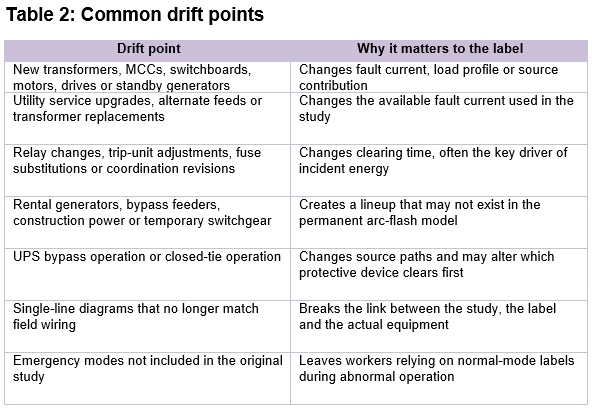
A practical configuration-control program should include:
- Current single-line diagrams: Source paths, ties, transformers, protective devices, transfer equipment, UPS paths, DER connections and major loads must match the field.
- Defined operating modes: Normal utility, generator backup, UPS bypass, PV import/export, closed-tie operation, maintenance shutdown and emergency temporary feed should be named conditions.
- Mode-to-study mapping: Each approved mode should identify applicable study assumptions, label basis, PPE guidance and engineering notes.
- Controlled switching changes: Switching orders, permits or procedures should identify when a lineup changes the arc-flash basis.
- Controlled protection data: Relay settings, trip units, fuse types, maintenance switches and coordination settings should be treated as safety-critical records.
- Defined review triggers: Source changes, protection changes, equipment additions and temporary power arrangements should trigger engineering review.
OSHA’s arc-flash guidance emphasizes hazard identification, assessment, prevention, control, worker participation and access to up-to-date safety information — exactly the management structure needed when labels depend on operating mode.
Labeling strategies for multiple operating modes
Multimode labels: Multimode labels work when equipment is routinely operated in a limited number of defined configurations, such as normal utility, generator backup or closed-tie operation. Instead of forcing one value onto equipment with more than one hazard profile, the label identifies the incident energy or PPE requirement for each approved operating mode. This strategy is useful only when the modes are clear, controlled and easy for the qualified worker to verify in the field.
Worst-credible-case labels: Worst-credible-case labeling gives the worker one conservative value based on the most severe realistic operating condition. This can simplify field decisions in plants where operating modes change often or where workers cannot easily verify the active source configuration before work begins. The tradeoff is that overly conservative labels can drive higher PPE, larger boundaries, longer setup times and more restrictive work planning than some tasks require.
Supplemental operating-mode signage: Supplemental signage is useful when the arc-flash label cannot fully explain the condition that makes it valid. Switchgear, transfer switches, UPS bypass cabinets, tie breakers, generator paralleling equipment and motor control centers may need direct field prompts such as “verify tie position before energized work” or “label applies to normal utility mode only.” The purpose is to interrupt assumption at the point of work.
QR-coded study references: QR codes can connect the field label to controlled documentation such as single-line diagrams, study cases, switching procedures, equipment records or revision history. This is valuable for supervisors, engineers and qualified workers who need fast access to current arc-flash information without searching through binders or disconnected files. The limitation is practical: devices may be unavailable, restricted, damaged, out of service or difficult to use in PPE.
Temporary labels: Temporary labels should be used when a temporary electrical configuration creates a real exposure that is not covered by the permanent label. Rental generators, bypass feeders, construction power, temporary switchgear and commissioning lineups can change available fault current, source paths and clearing behavior. The common failure is allowing “temporary” power to remain in place without temporary hazard communication.
Stop and verify labels: Stop and verify labels are appropriate when equipment can be fed from more than one source or when the arc-flash value depends on a condition that is not obvious from the equipment face. This includes double-ended switchgear, UPS-fed equipment, PV backfeed paths, closed-tie systems and transfer arrangements. The label should tell the worker what must be verified before relying on the arc-flash information, not simply warn them that danger exists. This strategy only works if the worker has authority to pause the job and a clear escalation path to engineering, operations or supervision.
More information is not automatically safer. The label must be legible, durable, located where the decision is made and written for the person standing in front of energized equipment.
Arc-flash label are the start of the decision
The arc-flash label should never be treated as a shortcut around the question that matters most: Is the system in the condition the label assumes?
In a simple, single-source installation, that answer may be easy. In a plant with generator backup, UPS bypass, PV export, closed ties, temporary feeds and maintenance lineups, it requires operating-mode discipline.
The safest facilities connect engineering studies, field labels, switching control, protective setting records, lockout/tagout and worker verification. They do not ask the label to carry information the plant has failed to control.
The goal is not more paperwork. It is preventing a worker from trusting a precise number that belongs to the wrong electrical lineup. In a multisource plant, arc-flash safety depends on more than the label. It depends on knowing which system the label describes.