Selecting valves for viscous fluid service is not as straightforward as it may appear. The valve must support variance caused by system variables like temperature and pressure drops.
Learning Objectives
- Understand the basics of fluid types to determine which valve to select.
- Learn about the different types of valves that can be used with viscous fluids.
Valve insights
- When used in manufacturing environments, valves should be carefully selected when picking them for viscous fluid services.
- There are several types of valves to choose from, including choke, globe-type and butterfly valves.
Selecting valves for viscous fluid service is not as straightforward as it may appear. Apart from achieving the desired flow coefficients, the valve must support the variance in viscosity caused by system variables like temperature and pressure drops.
Fluid types and their behaviors
Process engineers have to deal with different fluids bearing different coefficients of viscosity, which dictate their flow characteristics. The viscosity of Newtonian fluids varies as the volumetric flow rates or process temperatures change. Typical piping systems convey Newtonian, non-Newtonian, compressible or incompressible fluids and contain straight pipes, fittings and valves for controlling flow conditions.
As viscous fluids flow past these components, the system experiences pressure drops due to frictional losses and rapid changes in direction. Viscous fluids can plug small valve orifices, leading to the accumulation of small solid particles that impede normal fluid flow operations.
When designing or selecting valves, engineers pay attention to process variables, coefficients of viscosity of the working media and the desired type of flow. Engineers need to ascertain the compatibility of the valve material with the fluid media, durability (valve’s lifecycle), response time and the valve’s maintainability.
Effects of viscosity on valve performance
The fluid’s viscosity determines how fast it will move through a piping system. When dealing with the performance of different valve types, engineers evaluate their sealing efficiencies, pressure drops, flow and loss coefficients. Viscosity affects these performance parameters with direct and indirect implications on the integrity and safety of piping systems.
Valves on the path of the flowing fluid are obstacles that increase resistance to flow. Internal valve components increase the roughness of the piping system by providing additional fluid contact surfaces. As viscous fluids flow past the valves, there is a sharp rise in the number of frictional shear forces.
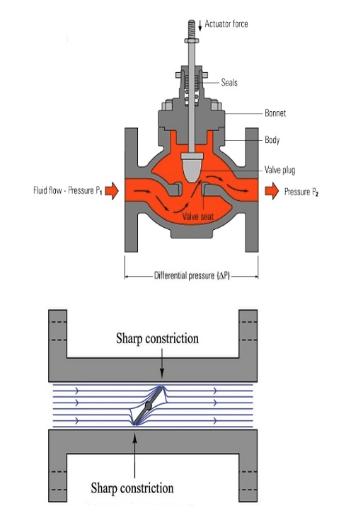
Valve components do not add or boost the energy of the working media; instead, they remove some potential and kinetic energy from the system. It results in a significant pressure drop across the valve. When the magnitude of the pressure drop across the system is high, there is an increased restriction to fluid flow past the valve. The movement of fluids due to inertia between different layers drops, causing clogging around the valve body.
Viscosity is responsible for erosion-corrosion of the valves used for viscous fluid service. When clogging occurs around valves, more foreign material and debris accumulates within the valve body. Moving viscous fluids past the valves at high process speeds accelerates the corrosive action of the particles. Corrosion leads to premature damage of seals, stem packings, valve seats and actuators.
Oil and gas production facilities rely on choke valves to control flow and regulate downstream pressure. These valves handle a mixture of solids, oil, gas and water. Choke valves reduce the operating pressure and increase the velocities of fluids. As the valves convey fluids, the solid particles erode valve components, which reduces the valve’s lifetime.
Piping systems utilize pumps to increase the pressure of viscous fluids and improve their flow rates. The pumps work with the assistance of throttling valves which control flow rates. With this setup, the pumps operate with the valve opening, closing or throttling to permit fluid flow at the desired levels.
For viscous fluid flow service, the throttling valves are kept at a partially-closed position. They remain partially closed even when there is a requirement for maximum system flow rates. It induces additional frictional losses on the flow and increases the demand for actuation energy to overcome the resistance to fluid flow. Subjecting valves to excessive and continuous throttling increases their susceptibility to cavitation.
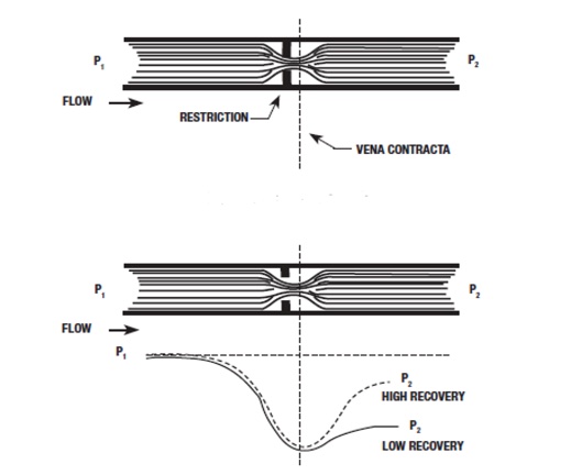
When viscous fluids move past the constricted portions of a valve (vena contracta), their kinetic energy/average velocities increase while the pressure drops. To maintain a steady fluid flow past the valve, the velocity at the vena contracta should be the greatest for the entire system. Once the fluid reaches the wider portions of the valve, it restores the pressure.
In some situations, the pressure of the fluid drops below its vapor limit and causes flashing within the valve. Flashing is the boiling phenomenon of the viscous fluid at the constricted sections of the valve. The boiling action results in a quick expansion of fluids, leading to a choked flow at the valves. Choking lowers the coefficients of flow at the valves. Choked flow conditions manifest when the pressure drop across the valve increases above the flashing point. The boiling fluid then moves past the plug and the seat, eroding the components over time.
Valves have movable mechanical parts with allowable degrees of friction between them. To actuate the valve, the stem of the valve must move from its static position. A considerable amount of force is required to overcome the static friction and the dynamic friction the fluid exerts on the valve. Fluids with higher coefficients of viscosity need larger actuation forces to overcome frictional resistance. These systems require automated actuation systems such as hydraulic or pneumatic actuators, which supply sufficient actuation forces.
Selecting the right valve for viscous fluid service
The flow coefficient (Cv) of a valve measures its efficiency to permit fluid flow. It relates the pressure drop between the valve and the allowable flow rates and varies with the size and type of valve. When sizing valves for semi-turbulent or laminar fluid flow, it is vital to factor in fluid viscosity, which impacts pressure drops across a valve. Process engineers utilize viscosity correction factors (Fv) to correctly size valves for viscous fluid service.
One way to address flow coefficient is to increase the size of the orifice. Although this seems like an ideal solution for viscous flow, it has potential drawbacks. Increasing the size of the valve is not only expensive, but it also increases particle retention volumes and induces significant velocity losses. Choosing the correct valve type and size guarantees sufficient flow throughout the system and limits the negative impacts of viscous flow.
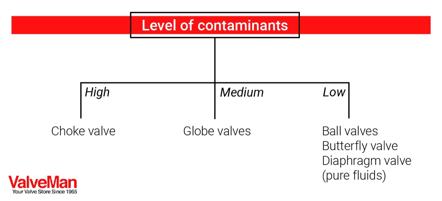
The first thing process engineers must evaluate before settling on a specific valve type is the quantity of contaminants in the service fluid. They must analyze the fluid’s physical and chemical properties to quantify the levels of contaminants. Contaminant levels fall into high, medium or low categories. A choke valve will be the most viable option for contaminated viscous fluids. Other options include ball valves and globe valves.
Valves explained
Ball valves provide excellent flow coefficients and induce minimal pressure drops on the system, making them the preferable flow control devices for viscous fluids and slurries in most industrial and oil and gas operations. They have smooth and unobstructed flow paths, as well as superb sealing characteristics that extend throughout their service life. For ball valves, pressure drops occur between the ball and the seat of the valve.
Some ball valves utilized for viscous fluid service contain liquid O-rings to enhance their sealing properties. Advanced ball valves use perfluoro alkoxy alkanes/polytetrafluoroethylene (PFA/PTFE) for their constructions to avoid O-ring sealing.
Diaphragm-type valves provide good flow coefficients, but they rank lower than ball valves. The design and construction of the diaphragm valve aim to limit contamination and the accumulation of solid particles around the valve body. It uses a metal pin to connect the membrane of the valve to the actuation system. The contact between the membrane and the valve seat creates an airtight seal. These valves are common in high-purity fluid applications because of their rapid shut-off, precise actuation capabilities as well as their cleanliness.
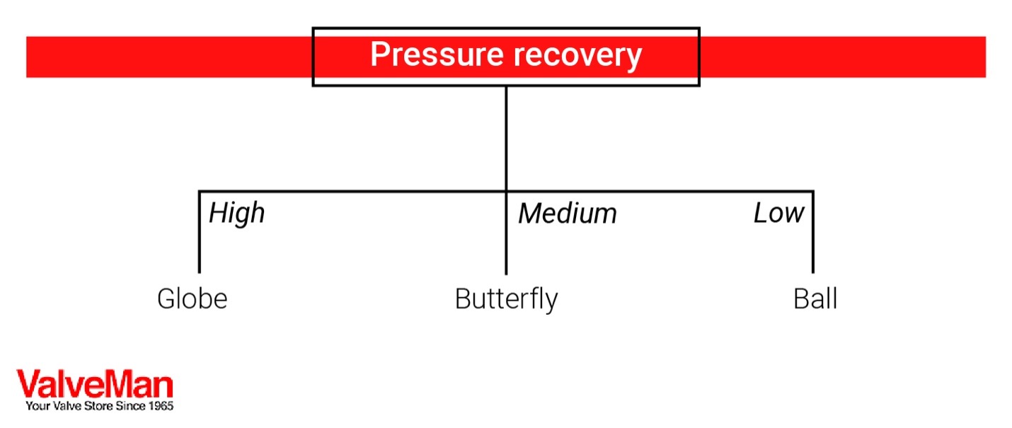
The other factor to consider in the selection process is the desired pressure recovery factors. Valves with low-pressure recovery protect piping systems from the dire effects of flashing. Engineers will settle on ball valves if the piping system in place has low levels of contaminants, requires medium precision control and pressure recovery is low.
When selecting valves, engineers have to predict the possibility of flashing occurring in a control valve. They rely on the pressure recovery factor that compares the pressure drops across the inlet and the outlet of the valve against the pressure drop from the inlet and the minimum pressure point of the valve. A valve with a high-pressure recovery factor is prone to flashing. The pressure recovery factor relies on the style and design of the valve. Valves with convoluted fluid paths present more opportunities for the dissipation of energy, which causes significant pressure losses.
By comparison, globe valves distribute pressure losses better than butterfly valves. A globe valve has several constriction points that facilitate even distribution of the effective system pressure drops. For a butterfly valve, the pressure drops occur at limited constriction points between the valve body and disc. Butterfly valves recover fluid pressure and have a lower pressure recovery factor, making them unsuitable for the conveyance of viscous fluids with lower vapor pressure limits.
Cavitation often happens after instances of flashing within the valve. Preventing these events requires proper pressure control throughout the system, so the pressure levels within the contracted valve sections do not fall beyond the vapor pressure of the viscous fluid. There are multiple ways for achieving this:
-
Relocate valves to high-pressure zones of the process to increase downstream and upstream fluid pressure.
-
Utilize control valves with low-pressure recovery characteristics — they guarantee higher pressure recovery factors. Ball-type valves have high-pressure recovery capabilities compared to globe-type valves. Although ball valves provide better sealing, flow applications prone to cavitation are likely to utilize globe-type valves.
-
Where possible, install multiple valves in a series to minimize the lowest pressure intensities of each valve.
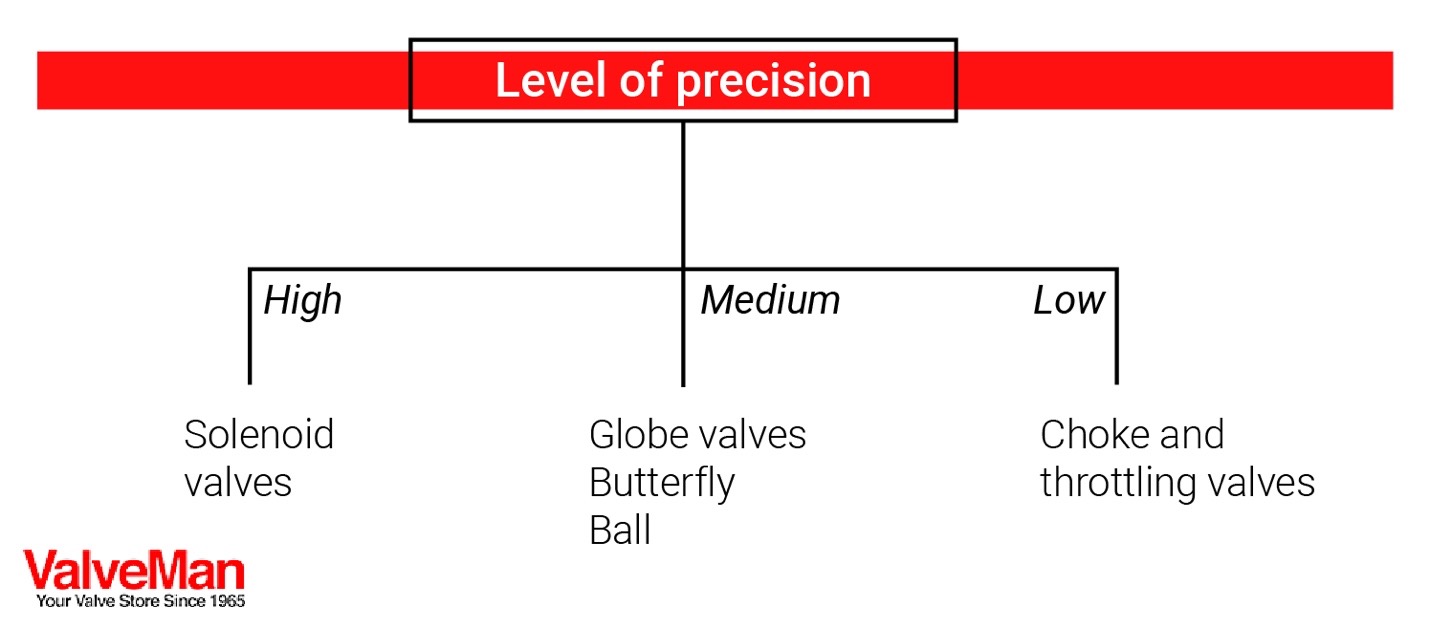
The other thing engineers evaluate during the valve selection process is the level of desired precision. High-precision flow processes often require automated valves that respond to flow conditions. Fluid flow processes requiring the highest levels of precision will utilize solenoid valves.
Some high-precision pipeline systems transport highly-viscous fluids under high pressure. These systems must maintain constant flow rates and retain minimal pressure drops across the valves. Most of these automated piping systems use solenoid valves that capitalize on the weaknesses of conventional quarter-turn valves.
Coaxial solenoid valves facilitate safe fluid control for components like heavy oils, grease or slurries. The viscous fluid media requires large forces to push the thick fluids past the valve. Coaxial solenoid valves are installed concentrically to internal service pipes. A magnetic plunger connects to the internal pipes, whose motion is parallel to the direction of flow of the viscous fluid.
System pressure is inconsequential to the operation of the solenoid valves. The lateral movement of the plunger causes the valve to open or close and control the flow of the viscous media.
When choosing coaxial solenoid valves for an industrial application, consider the pressure specifications of the valve ports, the size of the orifice and the compatibility of the valve material with the media.
ValveMan is a CFE Media and Technology content partner.