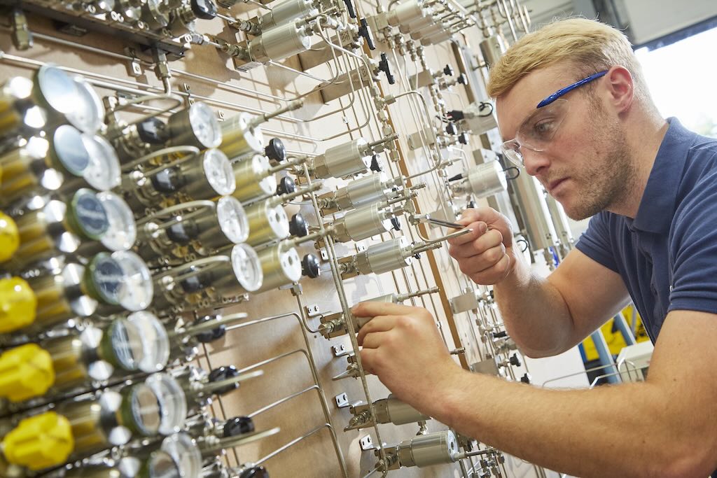
Valves are mechanical devices consisting of a body internally machined with cylindrical chambers and passageways. The chambers may contain pistons, spools, poppets, balls, and springs.
Valves are mechanical devices consisting of a body internally machined with cylindrical chambers and passageways. The chambers may contain pistons, spools, poppets, balls, and springs. Arrangement of the passages in the body together with the movement of the piston or spool diverts the fluid flow (Fig. 1).
As the spool moves in its chamber, some ports are closed while others are opened. Each position of the spool changes flow direction. Volume of flow and pressure are also affected by the movement of components within the valve body. The name of a valve is based on its usual function and is illustrated by a symbol (Fig. 2).
Types
Relief valves are required in any hydraulic circuit that uses a positive displacement pump to protect the system against excessive pressure. The valve is connected between the pump outlet and tank. It is normally closed and set to open at a pressure slightly higher than the system requires. It diverts pump delivery to the tank when this pressure is reached.
Pressure-reducing valves regulate the normal operating pressure of a main circuit to a lower setting required in a branch circuit. As soon as the desired pressure is reached in the branch circuit, the valve partially closes and allows just enough fluid through to maintain the desired pressure. The valve is adjustable and can provide any pressure in its range.
Sequence valves control the order of operation between two branches of a circuit. They regulate the operating sequence in a predetermined order based on pressure signals. Fluid is directed only to that part of a system connected with the primary port of the valve until the pressure setting is reached. The valve then directs fluid to the secondary branch.
Counterbalance valves are used to maintain an adjustable resistance against flow in one direction, but permit free flow in the opposite direction. The function of the valve is to prevent uncontrolled movements or to support a weight in one part of the system while fluid is made available for working components in other parts of the system.
Unloading valves are most often used on two-volume circuits, where a large quantity of fluid at low pressure is required for one portion of a cycle, and a relatively small amount is required at high pressure during another part of the cycle.
Check valves can provide directional or pressure control, or both. Often a check valve is nothing more than a ball and seat, sometimes with a spring, placed between two ports.
As a directional control, it has free-flow and no-flow directions. Flow through the seat pushes the ball away and permits free flow. Flow in the other direction pushes the ball against the seat, pressure forces it to seal the passage, and flow is blocked.
When used to create back pressure, a spring is placed next to the ball. Pressure at the inlet balances against the spring force to produce a pressure difference, depending on the spring rate.
Directional control valves consist of a body with internal flow passages connected and disconnected by a moveable part. This action results in the control of fluid direction. Various valve configurations are used, depending on the component to be controlled and control actions desired. Passages in the valve establish the number of ways flow can be diverted. The number of positions to which the valve can shift is determined by the configuration, and actuation mechanism.
A two-way directional valve provides an on-off function. This function is used to serve as a safety interlock or to isolate and connect system circuits.
A three-way directional valve is used to pressurize and drain one actuator port. When the spool is in one extreme position, the pressure passage is connected to the actuator port. In the other extreme position, the spool connects the actuator port with the tank or exhaust line.
A four-way directional valve reverses the motion of a cylinder or fluid motor. It has a pressure passage, two actuator ports, and tank or exhaust connection. The spool connects one or the other port to pressure, while the opposite port is exhausted.
Needle valves are one of the simplest adjustable flow control valves. They are available in all shapes and sizes with or without an integral check valve. Adding a check valve permits free flow in one direction and throttled or metered flow in the other. The flow rate is determined by the pressure and temperature of the fluid.
Pressure compensated flow controls are used in applications that cannot tolerate a wide range of actuator speeds due to load variations causing pressure changes. These flow controls vary their orifice to compensate for pressure variations and maintain a set flow rate.
Temperature compensated flow controls counteract changes in oil viscosity and temperature by altering flow rates through orifices. Sharp-edged control orifices or expansion rates of dissimilar metals are used to maintain a constant flow rate.
Actuators
Various methods or combination of approaches are used to activate a valve. They may be operated manually, mechanically, electrically, pneumatically, or hydraulically.
Plant Engineering magazine extends its appreciation to Anton H. Hehn, author of Fluid Power Handbook ; and Mead USA for the use of their material in the preparation of this article.
— Joseph L. Foszcz, Senior Editor, 630-320-7135, [email protected]
Hydraulic direction-control valve problems
Problem Possible causes
Faulty or Worn or binding control linkage
incomplete Insufficient pilot pressure
shifting Burned out or faulty solenoid
> Defective centering spring
> Improper valve spool adjustment
Cylinder Valve spool not centering
drifts Valve spool not shifting completely
> Valve spool or body worn
> Valve seats leaking
> Cylinder piston seals leak
Cylinder drops Loose lines between cylinder
load with valve and valve
spool centered O-rings on lockout or holding
> valve leak or are damaged
> Broken springs on lockout or
> holding valve
Relief valve leaks
Cylinder drops Spool valve position improperly
load slightly adjusted
when raised
Pneumatic valve problems
Problem Possible causes
Valve blows to exhaust Inlet poppet not sealing
when not actuated Faulty seals
> Faulty valve-to-base gasket
> Cylinder leaks
Valve blows to exhaust Faulty valve-to-base gasket
when actuated Faulty seals
> Damaged spools
> Cylinder leaks
> Supply pressure too low
> Water or oil contamination
Solenoid fails to actuate Loose pilot cover or faulty
valve, but manual solenoid
override does Low voltage
Solenoid and manual Faulty seals
override fail to actuate Varnish deposits in valve
valve Pilot pressure too low
> Water or oil contamination
Airflow is normal only Broken return spring
in actuated position
Solenoid buzzes Faulty solenoid
> Low voltage
> Varnish deposits in valve
Solenoid burns out Varnish deposits in valve
prematurely Incorrect voltage
Pilot section blows Loose pilot cover
to exhaust Pilot poppet not sealing
Poppet chatters Supply pressure too low
> Low pilot or signal pressure
> Faulty silencer/muffler
Valve action is sluggish Faulty seals on spool valve
> Varnish deposits in valve
> Supply pressure too low
> Low pilot or signal pressure
> Poor or no lubrication
> Faulty silencer/muffler
> Water or oil contamination
Flow control valve Excessive lubrication
does not respond Incorrect installation
to adjustment Dirt in valve
Frequently asked questions
Q: Under what conditions should an external pressure supply be used to feed solenoids on a directional valve?
A: There are several possibilities: When the pressure passing through the power section of the valve is insufficient to shift the spool, when the medium passing through the power section would be detrimental to the solenoid operator, or where the operating medium could not be exhausted.
Q: What are the advantages of pressure actuation over solenoid actuation?
A: Solenoid actuation requires the presence of electric switches, wires, and shielding necessary to reduce spark hazards and personal risk. Pressure actuation only requires three-way pilot valves and tubing. There is no spark or shock risk.
Q: What is a detented valve and how is it used?
A: A detented valve holds its position by mechanical means, such as a spring, ball, or cam. Also, detents are used to locate the middle position in three-position valves.
Q: Is it possible to convert a pressure signal into an electrical signal?
A: Pressure-to-electric switches turn a pressure signal into an electrical signal.
Q: What are the advantages of a five-ported, four-way pneumatic valve over a four-ported, four-way valve?
A: Five-ported valves have separate exhaust ports for each cylinder port. If exhaust silencers with built-in speed controls are used, speed of a cylinder may be individually controlled in each direction. Also, five-ported valves can function as dual pressure valves where air flows from the exhaust ports to the cylinder and the inlet port is used as a common exhaust.
Q: What is the difference between a three-way and four-way valve?
A: Three-way valves have one power output; four-way valves have two power outputs. Generally, three-way valves operate single-acting cylinders and four-way valves operate double-acting cylinders.
Q: What are manual overrides used for?
A: Manual overrides permit actuation of directional valves without using switches or pilot valves. In this way, a circuit may be tested without actually moving machine elements.
Q: What is the difference between a three-way, normally closed valve and a three-way, normally open valve?
A: Normally open valves allow pressure to pass when not actuated. Normally closed valves allow pressure to pass only when they are actuated.
Q: How is the right valve selected to control a cylinder?
A: There are many factors that contribute to the performance of a cylinder: quantity and type of fittings, tube size and length, load, and pressure. Manufacturers can supply general guidelines for selecting valves.
Q: Is there a valve that will direct pressure coming from either of two sources to a single destination?
A: A shuttle valve has three ports — two for different incoming pressures and one outlet port.
Q: How can piping be reduced and troubleshooting simplified when using a group of valves?
A: Have valves mounted on a manifold to take advantage of a common inlet and exhaust and centralized controls.
Q: What is the difference between two-position and three-position valves?
A: In a two-position, four-way directional valve the two output ports are always in an opposite mode. When one is receiving pressure the other is connected to the exhaust port. When actuated, a three-position valve functions the same way. However, a center position is provided that usually blocks all ports (pressure held), or connects both output ports to the exhausts (pressure released).
Control valve usage
> PRESSURE DIRECTION VOLUME
> Pneumatic Hydraulic Pneumatic Hydraulic Pneumatic Hydraulic
Relief Relief Check Check Needle Needle
> Pressure Pressure Pressure
reduction reduction Two way Two way — compensated
— Sequence Three way Three way — Temperature
> compensated
— Counterbalance Four way Four way — —
— Unloading — — — —