As variable frequency drives (VFDs) become increasingly common in motor applications, the rise in harmonic distortion imposed on the power system by these drives must also be mitigated accordingly.

Learning objectives
- Learn how variable frequency drives (VFDs) impose harmonic distortions.
- Review guidelines to determine an acceptable level of harmonics.
- Evaluate solutions to mitigate harmonic effects on a distribution system.
VFD insights
- Variable frequency drives control motor speed by converting incoming ac power to dc and back to a pulse-width-modulated ac waveform, a process that introduces harmonics, which can distort voltage and current throughout an electrical system. V
- FD-related harmonics are governed by IEEE 519 limits and can be addressed through mitigation strategies ranging from multipulse or active front-end drives to reactors, filters and transformers, selected based on cost, footprint and system performance priorities.
Variable frequency drives (VFDs) are commonly used to apply speed control to a motor as it starts, accelerates, decelerates and stops. Multiple topologies of VFDs are available, including a voltage-source inverter (VSI), current-source inverter and cycloconverter or matrix converter; the most common of these topologies is VSI.
VFDs with VSI topology operate via three major steps.
- The first step is the rectifier, which will take the incoming alternating current (ac) power and convert it to direct current (dc) power (see Figure 1). This can be with diodes in a bridge rectifier or insulated-gate bipolar transistors.
- The second step is the dc bus filter, which consists of inductors and capacitors that take the dc power and smooth out the waveform.
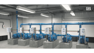
- The third step is the inverter section, which takes the smoothed-out dc power back into a pulse width modulated ac waveform (see Figure 2). This step controls the speed of the motor by modifying the duration of the on/off cycles to attain the desired speed. These drives are useful for applications where the motor needs to run at a demand-based rate (e.g., water pumps).
This process of converting the ac inputs into dc power (and back again) creates current draws in nonlinear pulses, instead of the sinusoidal voltage waves that come into the drive. This pulsed current draw includes harmonics that, in turn, cause voltage harmonics because of the voltage drop through upstream system impedances. Harmonics consist of the integer multiples of the fundamental frequency (e.g., third, fourth, fifth), as shown in Figure 3. For example, a third harmonic on a 60-hertz (Hz) system would be 180 Hz.

For three-phase systems, these harmonics can be classified into three different categories, each causing different issues.
- Positive sequence harmonics have the same phase sequence as the original three-phase signal, but phase shifted by increments of 120 degrees. These can cause a motor to run faster than the intended speed from the fundamental frequency.
- Negative sequence harmonics have the opposite phase sequence of the original three-phase signal phase that was shifted by increments of 120 degrees. These can cause a motor to run slower than the intended speed.
- Zero sequence harmonics induce a higher current into the neutral conductor (assuming a neutral conductor is present, such as in a four-wire, three-phase wye system).
In a balanced three-phase load, the neutral current is ideally close to zero. The third harmonic current and each multiple of it (Triplen harmonics), are added together as neutral currents — potentially overheating the neutral conductor. In a system without a neutral conductor, such as a three-phase delta system, the harmonics circulate inside the delta transformer and motor windings, thereby causing increased heat within these windings instead.
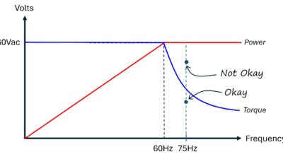
When not isolated, these harmonics propagate through the electrical distribution system, affecting not only the plant system but the system owner (e.g., the electric utility) as well. Inter-harmonics — frequency components that are not integer multiples of the fundamental frequency (e.g., 75 Hz on a 60 Hz system) — are not included in these considerations for two reasons:
- They are harder to model in harmonic analysis.
- They have a smaller magnitude and associated impact on the voltage distortion within a system.
Checking the harmonics threshold
While some magnitude of harmonics on a system is acceptable, a high enough level can cause overheating in windings, nuisance tripping of breakers and excessive current draw. As a result, equipment failures can occur (e.g., degraded transformers or interference in signals from sensors to supervisory control and data acquisition). The thresholds of acceptability are dictated by IEEE 519: Standard for Harmonic Control in Electric Power Systems and are evaluated at the point of common coupling (PCC). Refer to Table 1 – Voltage Distortion Limits and Table 2 – Current distortion limits for systems rated 120 V through 69 kV in the IEEE Std 519-2022 for these thresholds.

The PCC is the point in the power system that is closest to the system user where the system owner or operator could offer service to others. For industrial sites, this is typically the high-voltage side of the service transformer. For commercial/residential sites, this is typically the low-voltage side of the service transformers. These IEEE standards guidelines are categorized into voltage and current distortion.
Voltage distortion evaluates individual load harmonics and the total harmonic distortion (THD) on a system. The THD is defined in IEEE 519 as:
“The ratio of the root mean square (RMS) of the harmonic content, considering harmonic components up to the 50th order and specifically excluding interharmonics, expressed as a percent of the fundamental. Harmonic components of order greater than 50 may be included when necessary.”
The higher the voltage of the system, the stricter the limits are on harmonic voltage distortion.
Current distortion evaluates the maximum short-circuit current, maximum demand load current under normal operating conditions and total demand distortion (TDD). The TDD is closely related to THD; however, the ratio of the RMS of the harmonic content is expressed as a percentage of the maximum demand load current instead of the fundamental.
This maximum demand load current is “the sum of the RMS currents corresponding to the 15- or 30-minute maximum demand during each of the 12 previous months divided by 12.” Put simply, the greater the harmonic producing loads (e.g., VFDs) are, in comparison to the source capacity, the more impact the harmonics will have on a system and the stricter the limits are on harmonic current distortion.
Harmonic mitigation with VFDs
Several options can mitigate these harmonics to below the acceptable thresholds. Some of these options include mitigation directly at the source of the harmonics. For example, instead of a standard six-pulse drive, supplying a 12- or 18-pulse drive will generate harmonics of a higher order. In general, the magnitude of a harmonic will decrease as the order increases.
Therefore, a fifth order harmonic generated by a six-pulse drive will typically have a lower impact than an 11th or 17th order harmonic generated by a 12- or 18-pulse drive, respectively. Both options are typically more expensive and larger than a six-pulse drive, but will provide fully integrated harmonic mitigation.
An alternative technology to the pulse drives (available from many drive manufacturers) are active front-end (AFE) drives. Implementation varies among manufacturers, but the AFE drives generally use IGBTs for their rectifiers (active) instead of the diode rectifiers (passive) used in most drives. This allows for harmonic mitigation at the ac input by controlling the ac current from the source to a nearly sinusoidal current waveform. Some AFEs even support energy regeneration through motor braking. AFE pricing can be comparable to a 12- or 18-pulse drive and generally has a smaller footprint.

Line and load reactors can be added to drives to allow harmonic mitigation on both sides of the VFD; they are generally the cheapest harmonic mitigation option. The line reactor is located between the incoming power supply and VFD. These limit the harmonics, voltage spikes and transients coming into the VFD.
The load reactor is located between the VFD and motor. The reactor is sized based on the motor’s full-load amps and performs a similar function protecting the motor from harmonics, voltage spikes and transients. Both reactors are rated for the percent impedance (%Z) of the voltage system (typically 3% to 5%) and cause a corresponding voltage drop when running the full current rating (e.g., a 3% reactor will cause a 3% voltage drop).
As such, they are limited to the extent of their harmonic mitigation capacity by the voltage drop tolerance of the system and loads. A higher impedance reactor is preferable for longer cable runs and situations where the motor is more sensitive to harmonics. The reactors will typically expand the equipment footprint.
Line reactors and dc chokes are categorized similarly. The chokes are a drive add-on with comparable pricing and performance; they are located between the rectifier and dc bus and reduce the input current harmonics by smoothing the current waveform.
Drive isolation transformers (often the IEEE C57.18.10 H-factor transformers) can also be provided as an add-on harmonic mitigation tool. The transformers provide a sort of buffer between the power source and drive, adding inductive impedance to limit the voltage spikes generated by harmonics. These transformers can be better at addressing power quality issues than a line reactor and are generally more costly and require more space. The H-factor transformers are not to be confused with UL-rated K-factor transformers, which can be used to tolerate harmonics from smaller electronic loads but are not suitable for a drive isolation application.
Phase-shifting transformers offer a similar option, but instead of just acting as an air gap, the windings of the transformer themselves are configured to cancel out harmonics. While this provides more mitigation than the drive isolation transformers, this is usually a more involved solution that requires specific design to the harmonics being generated. If mitigating harmonics fifth order and above, a pair of transformers is needed and the load must be balanced between them. This is different than the 12- and 18-pulse phase-shifting transformers, which are part of the rectifier or front-end of a drive and work to reduce the harmonics on the input to the drive.
Some harmonic mitigation can be implemented at a source level, typically the bus directly upstream from the drive(s). These solutions have the advantage of applying to an entire source bus, rather than a per load application. As a tradeoff, these are often more expensive than the drive-level options and will require more engineering to determine sizing and implementation.
One of these source-level solutions is a passive harmonic filter. These essentially boil down to reactors and capacitors in “T” or “π” topology (LC or LCL resonant circuits) connected to the power source. As harmonics are propagated onto the bus from the drive(s), some will be drawn to the low-impedance LC circuit. This solution can come with some issues, such as poor power factor at low loading. In most cases, power needs to be disconnected if a motor runs in bypass instead of on the VFD.
Conversely, active harmonic filters act on a similar principle to the AFE drive products. The filters use current-sensing hardware to read the harmonics at the source. They then inject opposite currents to the harmonics to cancel them out. These are typically better than passive filters at achieving power factor correction to a desired level on a bus, but are more expensive. When compared to AFEs, they can be cheaper if many drives are being incorporated on the same source bus. Some manufacturers can even provide models that can be installed inside of motor center centers.
Generator design considerations
If a system (being added to) needs to operate on backup generator power, then it is not covered in the IEEE 519 because it is not a PCC. The acceptable harmonic distortion at generators should be evaluated with the generator manufacturer along with the specific loads expected to run in the backup scenario. In some cases, if the harmonic distortion exceeds the acceptable level for a generator, the alternator can be oversized to accommodate this. This employs the principle of lowering the ratio of load to source current that was also used by IEEE 519.
Given the range of options in addressing excess harmonics, it is prudent to consider which values (price, engineering time and footprint) are most important when weighing the pros and cons of each. Some may have a larger upfront cost for installation but can save money on reduced utility bills by moving the electrical distribution closer to unity power factor.
It can be worth it to install power analyzers and quality meters for this reason alone: just to monitor the effects of harmonics on a system. This is also a rapidly advancing field with new technology solutions identified regularly, so it is good practice to engage with equipment manufacturer representatives to keep abreast of the choices available.