A digital multimeter (DMM) is like an electronic tape measure for making electrical measurements. It may have any number of special features, but a DMM primarily measures volts, ohms, and amperes. This article provides the essentials required for selecting and operating this versatile tool.
Key Concepts
A 4
High-frequency noise from an adjustable speed drive can cause extremely inaccurate digital multimeter readings.
Don’t leave test leads plugged into the current input jacks when attempting to make a voltage measurement.
Sections: Selecting a DMM DMM basics Accuracy Digital vs. analog displays Making Measurements Resistance Continuity Capacitance Temperature Frequency Min/Max detection Diode test Measuring ac and dc current Input protection DMM safety
Sidebars: How to make voltage measurements How to make resistance measurements How to make current measurements Safety checklist Frequent DMM mistakes
A digital multimeter (DMM) is like an electronic tape measure for making electrical measurements. It may have any number of special features, but a DMM primarily measures volts, ohms, and amperes. This article provides the essentials required for selecting and operating this versatile tool.
Selecting a DMM
Choosing the appropriate DMM for the job requires not only looking at basic specifications, but also at features, functions, and the overall value represented by a meter’s design as well as the care taken in its production. Reliability is more important than ever today and a dependable DMM will have undergone a rigorous testing and evaluation program.
User safety is also a primary concern in the design of a good DMM (Fig. 1). Providing adequate component spacing, double insulation, and input protection helps prevent injury and meter damage if used improperly. A good DMM should be designed to the latest, most demanding safety standards.
DMM basics
Resolution, digits, and counts
Resolution refers to how fine a measurement the DMM can make. By knowing the resolution of a meter, you can determine if it is possible to see a small change in the measured signal. For example, if the DMM has a resolution of 1 mV on the 4-V range, it is possible to see a change of 1 mV while reading 1 V.
The terms digits and counts are used to describe a DMM’s resolution. A 3
It is more precise to describe a meter by counts of resolution than by digits. Today’s 3
Accuracy
Accuracy is the largest allowable error that will occur under specific operating conditions. Accuracy for a DMM is usually expressed as a percentage of reading. Specifications may include a range of digits added to the basic accuracy specification. This indicates how many counts the digit at the extreme right side of the display may vary. Typical basic accuracy for a DMM is between
Digital vs. analog displays
Theoretically, analog is continuous and infinitely divisible. An analog reading is absolute while a digital reading is an approximation. However, from a pragmatic perspective, the analog needle display is more subject to user error due to poor reading angle or scale interpretation. For accurate measurements in a practical setting, a digital display excels, quickly displaying an easy-to-read three or more digits for each measurement.
Making Measurements
Measuring voltage
One of the most basic DMM tasks is measuring voltage. Testing for proper supply voltage is usually the first step when troubleshooting a circuit. If there is no voltage present, or if it is too high or too low, the voltage problem should be corrected before investigating further (see “How to make voltage measurements”).
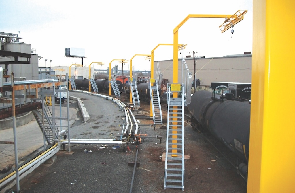
The waveforms associated with ac voltages are either sinusoidal, as with the sine wave associated with electrical power, or they are nonsinusoidal, as with sawtooth and square waves, ripple, and combinations thereof. These nonsinusoidal waveforms usually are the results of harmonics, such as those generated by some adjustable speed drives (ASDs). Quality DMMs display the root-mean-square (rms) value of these voltage waveforms.
The rms value is the effective or equivalent dc value of the ac voltage. Most DMMs are average responding — giving accurate rms readings if the ac voltage signal is a pure sine wave, but not accurately measuring nonsinusoidal signals. Only a DMM designated true rms up to its specified crest factor can accurately measure nonsinusoidal signals. The ability to make true rms measurements is increasingly important in today’s electrical work, given the large number of harmonic-producing nonlinear loads common in electrical circuits.
High-frequency noise generated by the pulse width modulated (PWM) circuitry on an ASD can cause extremely inaccurate readings on a DMM. However, some DMMs are now available with selectable low-pass filters and strong shielding required for accurately measuring motors controlled by ASDs (Fig. 2).
Resistance
Resistance is measured in ohms (Ω). Most DMMs measure down to 0.1Ω, while some measure as high as 300 MΩ (300,000,000 ohms). Infinite resistance (open circuit) means the resistance is greater than the meter can measure.
To prevent damage to the meter or circuit, resistance measurements must be made with the circuit power off (see “How to make resistance measurements”). Some DMMs provide protection in the ohms mode in case of accidental contact with voltages. The level of protection may vary greatly among different DMM models.
For accurate, low-resistance measurements, resistance in the test leads must be subtracted from the total resistance measured. Typical test lead resistance is between 0.2Ω and 0.5Ω. If the resistance in the test leads is greater than 1Ω, the test leads should be replaced.
If the DMM supplies less than 0.6 Vdc test voltage for measuring resistance, it will be able to measure the values of resistors that are isolated in a circuit by diodes or semiconductor junctions. This is possible because 0.6 Vdc is the voltage above which forward-biased semiconductors (silicon-based) conduct. This often allows you to test resistors on a circuit board without unsoldering them.
Continuity
Continuity is a quick go/no-go resistance test that distinguishes between an open and a closed circuit. A DMM with continuity checking capability allows you to complete many continuity tests easily and quickly. Most DMMs produce a tone or beep to indicate a completed circuit, which allows technicians to keep their eyes on their work instead of having to glance at a meter reading. The level of resistance required to trigger the beeper varies from model to model.
Capacitance
Capacitance is measured in Farads (F). Capacitance can be measured on small electronic components as well as large motor-starting capacitors. Some DMMs have a measurement range of 1nF to 10,000μF. Capacitors should be measured only after removing circuit power and safely discharging them.
Temperature
Some DMMs have the ability to measure temperature in Celsius or Fahrenheit using a thermocouple probe. Temperature plays a key role in the performance of electrical and electronic systems. DMMs that measure temperature can be used to troubleshoot temperature control systems, HVAC controls, overheating equipment, or processes that involve heating or cooling.
Frequency
Frequency is measured in Hertz (Hz), which is the number of cycles per sec of an ac waveform. Frequency measurement is important when working on ASDs, test equipment, control systems, and many other electrical and electronic applications.
Min/Max detection
Most DMMs have a Min/Max function to capture measurements that change too quickly for the user to notice. Min/Max constantly stores the lowest and highest readings even if that reading is very brief (less than
Diode test
A diode is like an electronic switch. It can be turned on if the voltage exceeds a certain level — approximately 0.6 Vdc for a silicon diode. A diode allows current to flow in one direction only. It is the fundamental component of rectifier circuits, which convert ac to dc.
Diode test mode sends a current through a semiconductor junction, and then measures the junction’s voltage drop. A typical silicon junction voltage drop is 0.5_0.8 Vdc. Use the diode test mode to check diodes, transistors, silicon controlled rectifiers (SCRs), and other semiconductor devices (Fig. 3).
Measuring ac and dc current
Current measurements are different from other DMM measurements. Current measurements taken with the DMM alone require placing the meter in series with the circuit being measured. This means opening the circuit and using the DMM test leads to complete the circuit so all the circuit current flows through the circuitry of the DMM (see “How to make current measurements”).
Input protection
A common mistake is to leave the test leads plugged into the current input jacks and then attempt a voltage measurement. This causes a direct short across the source voltage through a low-value resistor — called a current shunt — inside the DMM. A high current flows through the DMM and, if it is not adequately protected, can cause extreme damage to both the DMM and the circuit — and possible injury to the DMM user. Extremely high fault current can occur if higher voltage industrial circuits are involved (240 V or higher).
A DMM should have current input fuse protection of high enough capacity for the circuit being measured. For example, on a 480-V circuit, an 11-A, 1000-V fuse with appropriate interrupt capacity is required to clear the fault.
DMM safety
Making measurements safely starts with choosing the proper meter for the application and its environment (see “Safety checklist”). Carefully read the instrument user manual before use, paying particular attention to the Warning and Caution sections (see “Frequent DMM mistakes”).
The International Electrotechnical Commission (IEC) established safety standards for working on electrical systems. Make sure you are using a meter that meets the IEC category and voltage rating approved for the environment where the measurement is to be made. Choose a meter that also has been certified by a Nationally Recognized Test Laboratory (NRTL) such as UL, CSA, or certified European bodies such as VDE or TÜV. This certification means the meter has been independently tested and meets standards for both North America and Europe.
A DMM is one of the most versatile electrical tools. By choosing the appropriate DMM for the job and using it safely, electrical engineers, technicians, electricians, and other electrical professionals can perform a wide variety of measurements using a single device.
More Info:
If you have questions about the safe use of DMMs, contact the author. Harvey Trager can be reached at 425-446-6455 or [email protected] . For more information on DMMs and other electrical test equipment, go to plantengineering.com . Article edited by Jack Smith, Senior Editor, 630-288-8783, [email protected] .
How to make voltage measurements
Select Vac or Vdc , as desired.
Plug the black test probe into the COM input jack. Plug the red test probe into the V input jack.
If the DMM has manual ranging only, select the highest range to prevent overloading the input.
Touch the probe tips to the circuit across a load or power source (in parallel to the circuit).
View the reading, being sure to note the unit of measurement.
For dc readings of the correct polarity ( autopolarity will merely display a minus sign indicating negative polarity. With an analog meter, you risk damaging the meter.
Caution :Digital multimeters and their probe accessories are not intended for electrical utility applications in which high voltage (greater than 480 V) is also accompanied by high energy. Rather, they are intended for use in low-energy applications.
How to make resistance measurements
Turn off power to the circuit.
Select resistance (Ω).
Plug the black test probe into the Com jack. Plug the red testprobe into the Volt, Ohm, Diode Test input jack.
Connect the probe tips across the component or portion of the circuit for which you want to determine resistance.
View the reading, being sure to note the unit of measurementΩ, kΩ, or MΩ.
Caution :Make sure the power is off before making resistance measurements.
How to make current measurements
Turn off power to the circuit.
Cut or unsolder the circuit, creating a place where the meter probes can be inserted.
Select Aac or Adc as desired.
Plug the black test probe into the COM input jack. Plug the red test probe into the A or mA input jack, depending on the expected value of the reading.
Connect the probe tips to the circuit across the break so that all current will flow through the DMM (a series connection).
Turn the circuit power back on.
View the reading, being sure to note the unit of measurement.
Note :On meters with autopolarity, if the test leads are reversed for a dc measurement, a “-” will be displayed.
Safety checklist
Taking the time to think of safety before you use your DMM is a good habit to form. Follow these safety best practices when using your DMM:
Use a meter that meets accepted safety standards for the environment in which it will be used
Use a meter with fused current inputs and be sure to check the fuses before making current measurements
Inspect test leads for physical damage before making a measurement
Use the meter to check continuity of the test leads
Use only test leads that have shrouded connectors and finger guards
Use only meters with recessed input jacks
Select the proper function and range for your measurement
Be certain the meter is in good operating condition
Follow all equipment safety procedures
Always disconnect the “hot” (red) test lead first
Don’t work alone
Use a meter that has overload protection on the ohms function
When measuring current without a current clamp, turn the power off before connecting into the circuit
Be aware of high-current and high-voltage situations and use the appropriate equipment, such as high-voltage probes and high-current clamps.
Look for these safety features in a DMM:
Fused current inputs
Use of high-energy fuses (600 V or higher)
High-voltage protection in resistance mode (500 V or higher)
Protection against voltage transients (6 kV or higher)
Safety-designed test leads with finger guards and shrouded terminals
Independent safety organization (UL, CSA, etc.) approval/listing
Frequent DMM mistakes
Common situations that lead to DMM failure include:
Contact with ac power source while test leads are plugged into current jacks
Contact with ac power source while in resistance mode
Exposure to high voltage transients
Exceeding maximum input limitations (voltage and current).