How to ensure code requirements for hazardous environments are satisfied
Medium voltage (MV) equipment is commonly encountered in today’s petrochemical facilities. Electric motors operating at 2.3 kV to 15 kV are often deployed for larger horsepower equipment such as compressors and pumps.
Petrochemical facilities come with many unique challenges (see Figure 1). Principal among these is the presence, or possible presence, of flammable concentrations of gas in the atmosphere, or release of flammable liquids due to equipment failure.
Electrical systems installed in these demanding and hazardous environments must satisfy the requirements of NFPA 70-2020: National Electrical Code (NEC).
Specific requirements for MV wiring methods are often grouped at the end of relevant NEC articles. These MV requirements can either amend, or completely supersede the low voltage requirements. The design process can often require one to completely understand both the low voltage and the MV sections. Add the requirements for classified areas into this mix, and it is easy to see where confusion may set in. This article explains some of the more common aspects of MV cable installations in hazardous environments and how to ensure code requirements will be satisfied.
Conductor sizing
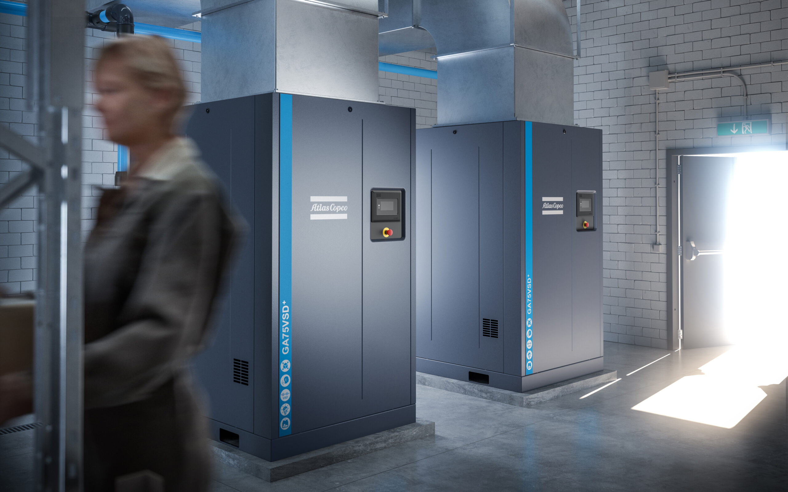
A typical MV motor feeder circuit often originates at a motor control center starter cubicle or a switchgear circuit breaker compartment. These are typically located in a non-hazardous location remote from the motor. From the source, one or possibly more MV cables are usually routed in cable tray to the load (see Figure 2). Because of the thickness of MV cable insulation and required bending radius due to the metallic tape shield, cable tray is most often preferred over conduit for MV applications (see Figure 3).
The conductors must be sized in compliance with NEC Articles 430 and 311 with necessary adjustments for cable tray fill and spacing per Article 392. Note that according to Article 430, MV motor conductors are not sized based on motor full load amps (FLA) as is done for low voltage motors, but instead selected based on the motor overload protection setting. Additionally, the grounding requirements for MV circuits are grouped at the end of Article 250. These requirements supplement and modify the previous sections of this long article. Note that cable selection based on ampacity requirements must be done according to the requirements of Article 311 factoring in derating for ambient temperature and mutual heating effects encountered in grouped underground installations rather than relying solely on manufacturers data sheet values.
Classified area considerations
Once the cables and cable tray are properly sized for the load served, requirements for the portion of the circuit that lies within the classified area must be considered. For this discussion, assume this scenario consists of the cable and tray going out to the load and the cable terminations at the load. The discussion s focused ion Class 1 Division 2 (C1-D2) Group D environments, which are common in petrochemical facilities. It will also touch on the differences between Division 2 and Division 1 installations. The requirements for electrical installations in hazardous areas are specified in NEC Articles 500 and 501 for North America, or alternately Article 505. Before the circuit design is approached, the classification, division, group and extents of the hazardous area must be evaluated. As required by NEC Article 500.4, this information is documented on area classification plans, details and often elevation drawings. The authority having jurisdiction (AHJ) will need this information to verify the adequacy of the electrical design.
With this background information in hand, the MV circuit design and material specifications can proceed. One question that is commonly asked at this point is “do I need a special MV cable type for classified areas?”
This is one of those areas where confusion often arises. In MV applications, “Type MV” cable is normally selected. The use, installation and construction of Type MV cable is detailed in NEC Article 311. However, if one looks in section 311.32, “Uses Permitted,” no mention of classified areas is found. However, below this list is an informational note stating the “Uses Permitted” is not an all-inclusive list.
One should search through Article 501 and read section 501.10 “Wiring Methods” to see that Type MV cable installed in cable tray with approved termination fittings is approved for C1-D2 locations. If your installation is in a Division 1 location, you may likely specify Type MC-HL cable. Furthermore, this cable is allowed only for industrial facilities with limited access and full-time qualified maintenance onsite. The “HL” stands for hazardous location. The “MC” stands for metal clad, so you will need to specify the correct fittings to properly terminate the cable armor. This is typically a cable gland.
Your C1-D2 cable specification should specifically state “Type MV” and include language requiring that the cable be approved for cable tray use and is sunlight resistant. Although these are fairly standard among manufacturers, having this stated up-front protects the end user from costly rework. Also the cable temperature rating should be specified. Usually this is either the 90 C rated MV-90, or the 105 C rated MV-105 type. The 105 C rating is usually selected to allow for better short-term overload performance and ability to withstand downstream short circuits in feeder applications. Unlike single conductor cables, 3 conductor type MV cables are usually also approved for direct burial.
Cable terminations and sealing
Once a cable is selected and sized, consider cable terminations at the load end. Assume this is designated as a C1-D2 location. Cable termination selection is a complex subject. The termination will be selected according to cable and conductor type, voltage level, indoor versus outdoor, load terminals, among other things.
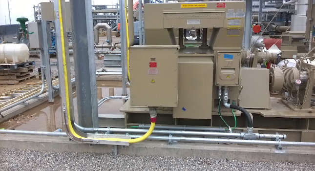
The size of the enclosure at the motor and whether current transformers (CTs) are required should be determined. Smaller motors often have terminal boxes that are quite confined. Another issue to be considered is most motor terminal boxes are set up for bottom cable entry and often cannot be rotated as with low-voltage motors. Be mindful of cable bend radius requirements found in NEC Article 300.34 (see Figure 4).
Figure 5: MC-HL cable with gland installed at a medium-voltage motor terminal box. Courtesy: Samuel Engineering[/caption]
If you are using a type MV cable, it gets a little more complicated. If you want to use a cable gland with an MV type cable, you will need to verify the gland is approved for this type of cable. Many are not. The other option is an explosion-proof conduit seal placed at the cable breakout. However, this approach is often challenging as well.
Installation of a conduit sealing fitting on larger size conduits is often difficult, particularly in the congested area around the motor terminal box. Removing the cable jacket and fillers at the seal fitting exposes the shields and insulation to possible damage. More so than low voltage tray cable, even minor damage to MV cable construction can lead to premature failure. It is probably best to have a discussion with the AHJ before this route is taken so that an acceptable strategy to minimize the potential for gas transmission can be established.
Acceptance testing
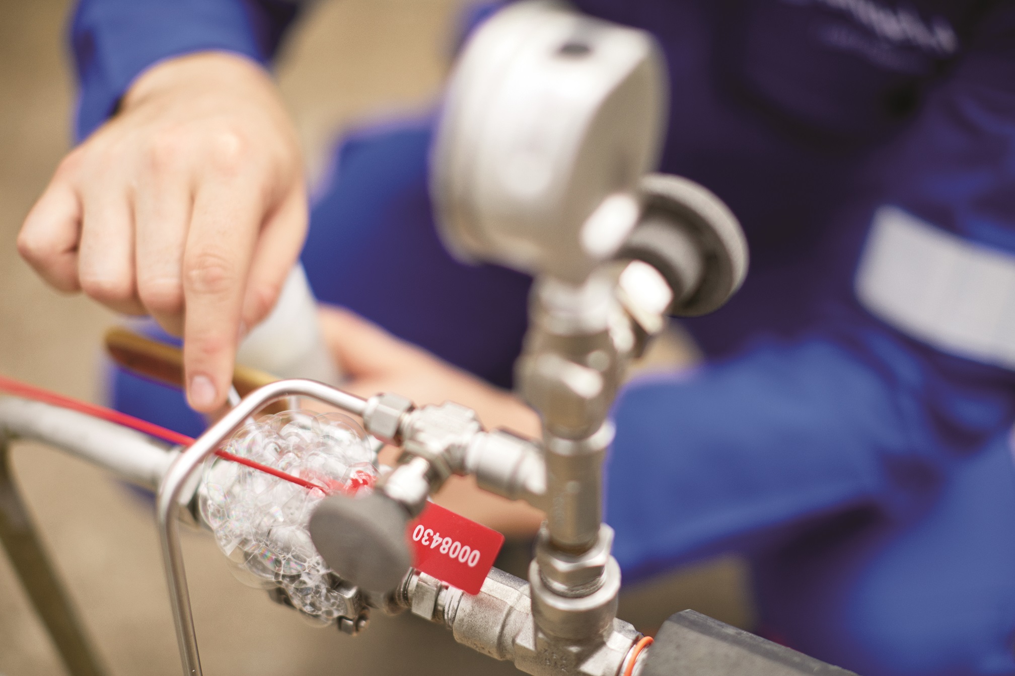
This leads to the final topic to be discussed: acceptance testing after installation. Most petrochemical plants typically require acceptance testing of MV cables before energization. Some also call for periodic maintenance testing. Usually, this is by means of high potential dc testing, or dc Hi-Pot. This topic is one with a wide variety of opinions and recommendations associated with it and the reader is encouraged to research the wealth of technical papers available and recommendations of cable manufacturers.
Generally, acceptance tests should be conducted in accordance with IEEE 576: IEEE Recommended Practice for Installation, Termination and Testing of Insulated Power Cable as Used in Industrial and Commercial Applications using the recommended voltage level for the cable insulation rating. This is typically considered a “go, no-go” test in that the actual test current leakage values are of less importance than the plotted curve shape with respect to the test time. The leakage values during the test should initially start out relatively high and fall to a stable value for the remainder of the test period, typically 15 minutes. Note that this type of testing is influenced by humidity, moisture in raceways and temperature. These conditions are difficult to control, and the test results should be reviewed by a person with experience in interpreting the results.
Final thoughts
Designing and installing MV cables in petrochemical facilities presents a number of challenges and requires a holistic approach to the entire installation. Specifically, a comprehensive design approach is warranted that includes an understanding of the MV cable construction, an understanding of the terminations, physical limitations of the load equipment and involvement of the AHJ to sort through the relevant NEC requirements.