The task of sizing a spring-and-diaphragm actuator for a control valve often introduces two terms: bench set and stroking range, which typically cause confusion.
The task of sizing a spring-and-diaphragm actuator for a control valve often introduces two terms: bench set and stroking range , which typically cause confusion. While both terms refer to a change in valve position, from fully closed to fully open, there is no direct relationship between the two (Fig. 1). Actuator sizing procedures consider only stroking range, which can be significantly impacted by valve packing friction.
Bench set
Bench set (expressed as a pressure range) is defined by two actuator pressures: That at which the actuator is at one extreme of travel, and a second pressure at which the actuator has traveled a prescribed distance. At the lower of the two pressures, the actuator spring is fully extended; while at the higher pressure the spring is fully compressed.
Bench set is measured without any load on the actuator. The actuator is not even connected to a valve for this procedure, since its purpose is to verify actuator operation.
Stroking range
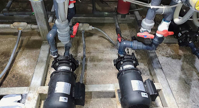
Stroking range is measured with a load when the actuator is mounted to a control valve body (Fig. 2). The actuator pressure range required to stroke the valve assembly is always different than the bench set pressures. This value is identified as stroking range. As with bench set, the stroking range is the change in pressure required to move the actuator from one extreme position to a prescribed location. However, required pressures can be significantly different than those for bench set because the actuator is handling a load.
For a given valve configuration in a particular application, the unbalance force and required seat load are constants with respect to actuator sizing. While proper actuator sizing allows for load forces, and in many cases introduces a safety factor, packing friction can undo the best sizing practices.
Total valve friction is the one component affected easily by incorrect or improper packing selection, installation, and maintenance. Packing friction decreases actuator force by using up the safety factor and by offsetting available seat load. If available seat load is impacted, the valve’s shutoff capability is compromised.
It is important to recognize that while a valve may stroke fully, the ability of its actuator to load the valve plug into its seat may have been reduced or eliminated. It is not uncommon for excessive valve leakage or trim damage to be traced to inadequate seat loading force. In these instances, the first area to review should always be actuator sizing, with a focus on valve friction.
Control valve packing
Until the late 1970s the criteria for designing, constructing, and evaluating valve stem packing had been quite simple: Strike a balance between packing box leakage and friction-related control issues. Up to that point, packing box leakage, although not desired, was not a significant concern for many process industries.
Valve users became cost conscious about material losses and EPA recognized that valve stem packing leakage contributed to pollution; therefore, valve stem packing performance became a significant issue in the 1980s. Up to that point, valve stem packing had been viewed as a commodity and the control valve manufacturer simply supplied whatever packing the customer requested.
This new interest in valve stem packing performance was the stimulus that prompted industry to develop low-friction packing systems that sealed and were predictable in performance. Although EPA concentrated on those processes that handle certain toxic or lethal chemicals, the natural progression was to improve all packing.
The two primary materials used in modern-day packing systems are plastics such as PTFE, used up to 450 F; and flexible graphite, used up to 1500 F. PTFE packing systems exhibit low-friction characteristics and generally seal well. Optimized versions have been introduced to handle those chemical applications that must be in compliance with EPA emission control requirements.
Friction-related problems in a control valve are usually associated with graphite packing systems. High-temperature graphite packing systems find use primarily in the power and hydrocarbon industries.
In the power industry, this packing is required for high-pressure and high-temperature applications. In the hydrocarbon industry, graphite is required for fire safety, as well as high-pressure, high-temperature applications.
Today’s packing systems
State-of-the-art packing systems available in the early 1980s were not totally acceptable for severe service applications (defined as high-pressure/high-temperature). After a considerable amount of R&D, basic packing design principles were developed and incorporated into today’s valve packing systems.
Packing systems intended for stringent emission control should incorporate the points listed in the section “Valve packing principles.” For less severe applications, other less-rigorous packing sets are used. Understanding the basic principles of a well-designed packing system provides the valve mechanic with the proper insight for packing selection, installation, maintenance, and repair.
Friction in high-temperature packing systems can vary considerably throughout its life. Generally, the highest friction values are associated with newly installed packing in a new or like-new control valve.
The actuator must have the power to overcome initial friction levels, as well as those occurring after the packing has broken in. It sometimes can be misleading if friction is measured after the break-in period without recognizing that at this time its level may be only 50% of the initially specified friction. For proper valve operation, the actuator must be sized to overcome the highest loads it will be required to handle.
— Edited by Joseph L. Foszcz, Senior Editor, 630-320-7135, [email protected]
What impacts stroking range
– Unbalanced force calculated by multiplying the unbalanced area in the control valve times the maximum process pressure the valve will experience.
– Required seat load based on plug-to-seat contact area for a given valve configuration and specified leakage class.
– Total friction in the valve, which is dominated by packing friction.
Valve packing principles
Subject the packing to a constant and correct amount of stress to achieve and maintain a seal. This action is accomplished using live-load springs, but only on a packing system designed to be live-loaded. Do not attempt to live-load packing that is not specifically designed for that purpose.
Use no more packing than the minimum amount required to affect a seal. This procedure minimizes the adverse effects of thermal expansion and reduces total packing friction.
Install less pliable anti-extrusion rings on either side of flexible graphite seal rings to prevent the packing from extruding out of the packing box.
Use guide bushings on the valve stem. In most control valve designs the packing itself acts a bushing to center the stem in the packing box.
Be sure the valve stem has a smooth, highly-polished finish to reduce packing friction and minimize leak paths.
More info
The author is available to answer questions about valve actuator sizing. He may be reached by fax at 515-754-3025 or
e-mail: [email protected].
Key concepts
Bench set refers to unloaded actuator motion; stroking range refers to valve/actuator assembly motion.
Packing friction reduces the amount of actuator force available to move a valve.
Actuators must be able to overcome packing friction when it is the highest — at installation.