At a large floating production storage and offloading unit (FPSO), managers have found a way to protect workers and equipment from electrical arc flash and reduce the risk of downtime.
Learning Objectives
- Understand the added risks of arc flash for floating production storage and offloading (FPSO) units.
- Learn about the unique risks for arc flash for FPSO units.
- Discover the proper ways to mitigate arc flash risks for FPSO units.
FPSO unit arch flash protection insights
- Arc flash protection is particularly important for floating production storage and offloading (FPSO) units given the delicate nature of these offshore operations.
- Risk factors for arc flash for FPSO units include exposure to humid, salty air and water, as well as extreme weather.
- Current protection is a good solution to mitigate the risk of arc flash for FPSO units.
Floating production storage and offloading unit (FPSO) operations require electrical power, which must be distributed safely and reliably. That’s why managers at a large FPSO took a proactive electrical safety role. This floating structure is located 10 miles offshore in the Atlantic Ocean. It processes more than 250,000 barrels of oil per day and is capable of storing more than 2 million barrels of oil.
Onsite power generation is required on FPSOs to power onboard equipment. Many protection schemes and methods are investigated to determine the most effective safeguards for the FPSO. These inspections include, but are not limited to short-circuit current, arc flash and system stability studies. The engineering firm performing the studies discussed the importance of arc flash mitigation on the FPSO in addition to addressing the short-circuit current. An electrical accident, such as an arc flash, in the presence of explosive gases, could be catastrophic to the operation and personnel.
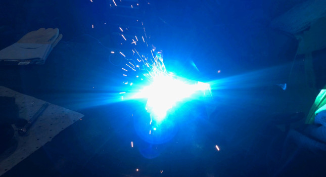
The perfect storm for arc flash
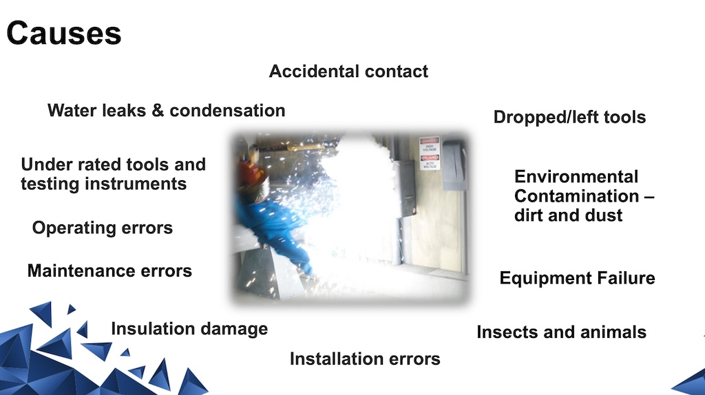
At sea, humid, salty air and water from extreme weather can increase the risk of electrical tracking and electrical arcs. Electrical tracking, or sometimes referred to as electrical treeing or dry banding, is a breakdown phenomenon in solid insulation caused by partial discharges over time, which “track” to the nearest electrode causing a short-circuit or arcing fault. Electrical tracking may occur in any energized piece of equipment including cables and switchgear. Therefore, it is a common practice in the electrical system to deliberately float or employ high-resistance grounding. These measures help mitigate the risk of phase-to-ground faults, which are responsible for the vast majority of arc flash events. Another advantage of this system design is the benefit of allowing operations the ability to ride through the fault.
However, a chance remains for phase-to-phase or three-phase arc flash events, which research shows are more likely to occur in the presence of maintenance workers due to movement in the area, and sometimes caused by a dropped tool, according to the National Fire Protection Association‘s “Occupational Injuries from Electrical Shock and Arc Events.” The danger to workers has made arc flash mitigation a priority.
Five types of arc flash mitigation
The managers and a consulting firm reviewed the available arc flash mitigation approaches and categorized them into five groups:
- Fault interrupting technologies include current limiting fuses, expulsion fuses, and circuit breakers. In the presence of fault current, these devices open the circuit by means of a fuse or a breaker. These devices are part of the normal infrastructure of any electrical system, and they work well at protecting equipment and personnel against overcurrents. Unfortunately, an emerging arc may not draw enough current at first to trigger an immediate operation. These devices may be designed or sized to ignore temporary and normal current spikes, such as inrush currents when a motor starts. In addition to triggering time, these devices require a finite time to operate, which may allow the arc to escalate into an arc flash.
- Arc diversion technologies include three-phase grounding switches. A grounding switch responds to an arc flash using a light sensor to detect an arc and introducing a bolted three-phase fault, typically upstream in the system.
- An arc flash relay uses the strategy of fast arc detection. Light sensors detect the light from an arc and within a few milliseconds, the relay signals the circuit breaker to open. The reaction time of an arc flash relay is limited by the time it takes the circuit breaker to open, which is up to 50 milliseconds for a typical molded case circuit breaker at continuous currents greater than 1,200 A.
- Current reduction technologies include current limiting reactors and high-resistance grounding. These devices reduce the amount of current in a fault by a specific percentage, which in turn reduces the available energy during an arc flash event. High-resistance grounding places a large resistor on the path to ground, which limits the current that can flow to ground to a low value, typically around 5 A. The high-resistance ground addresses single-phase arc flash but does not mitigate a phase-to-phase or three-phase arc flash.
- Triggered current limiter, also called a current-limiting protector, is an electronically controlled and sensed device that consists of a main continuous current conductor with a parallel-mounted, low continuous-current-rated current-limiting fuse. The current limiting protector interrupts the circuit within 0.25 to 0.50 of a cycle. The trigger threshold level can be adjusted if the electrical system is upgraded over the life of the triggered current limiter to ensure proper protection.
Selection considerations for arc flash mitigation
Each strategy has its advantages and disadvantages. Engineers know that fuses and circuit breakers are essential for overcurrent protection but cannot react to arcs quickly enough in every situation. For example, a typical high-speed current-limiting fuse (4,000-A rating) would operate quickly at less than 10 milliseconds during a high value fault (typically around 100,000 A), but would require more than 1 second to operate during a moderate value (30,000 A, typically) fault.
When operated, the grounding switch would subject associated equipment to electrical stress, possibly shortening equipment service life and potentially damaging the upstream equipment.
To provide effective arc flash mitigation to an FPSO, reactors require vast impedance that is not practical as they have a regulating voltage drop and consistent losses due to the copper windings.
The current limiting protector was not a well-known technology. Originally, it was designed for use by electric power utilities for medium-voltage applications. It was designed to operate the fastest of any of the arc flash mitigation technologies under consideration. It could be used on upstream medium-voltage equipment, extending protection to many electrical panels downstream. A common theme among FPSOs is to specify circuit breakers with an interrupt rating below the maximum available short-circuit current and include a triggered fault-current limiter to assist in managing the high levels of short-circuit current.
Current-limiting protectors fit the bill
FPSOs need technologies for arc flash protection that keeps workers safe, prevents equipment damage and reduces liability. In this case, a lesser-known technology provided the best solution that managers expect will maintain critical uptime and safety.
After a careful review of the options, the engineers recommended a current-limiting protector, which protects a bus tie, a typical application on an FPSO. If there is an arc flash event, the current limiter will reduce the energy, eliminating or greatly reducing the damage. Applying the current-limiting protector at other strategic locations in the system, such as directly on a transformer/generator, the energy may be reduced to 1% of its potential value. Having this protection also enabled managers to use lower rated switchgear, which saved on weight, space, and costs.
In this case, the consultant recommended the setpoint at 21 kA, above the expected inrush current levels. Because this was applied at the bus tie between numerous generators, operation of the protector would cut overcurrent to within the breaker ratings and approximately lower the arc flash energy to 25% of its peak value. This was enough to protect the equipment and to mitigate arc flash at that location. In cases where the setpoint is relatively high, secondary arc flash protection, such as arc flash relays may be applied at downstream electrical panels. But in this case it was not necessary.
Arc flash explained
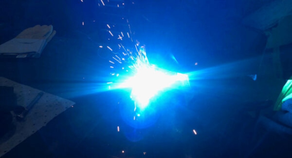
An arc flash occurs when electricity crosses an air gap to find a path to ground or another phase in the circuit. The arc starts small, but as it grows, the heated metal conductors vaporize and create a cloud of ionized gas that conducts all the current available to that circuit. The results of high current and expanding gas are intense heat and an explosion-extremely dangerous to workers and destructive to equipment. In addition, the costs of downtime at sea likely would be higher than for land-based refineries due to the difficulty and delays of delivering replacement gear offshore.

