Arc flashes are responsible for about 80% of electrical accidents in the U.S. each year.

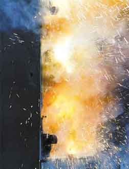
Arc flashes happen when an electric current passes through the air between two conducting metals—an arc fault. Almost instantly, an arc can superheat the air around it to a temperature up to 35,000 F—about four times the sun’s surface temperature. This extreme heat ionizes all nearby materials, including copper, insulation, and metal enclosures, creating explosive gaseous plasma as those materials expand to many thousands of times their solid volumes.
Under these conditions, the copper changes to plasma, with a volume about 67,000 times that of its solid form. Or, stated differently, each cu in. of copper converts to almost 39 cu ft. of copper vapor.
Arc faults are different from bolted faults on the load terminals of standard, metal-enclosed switchgear. Switchgear equipment is designed to withstand bolted fault currents until circuit breakers or fuses interrupt the current flow. When a bolted fault occurs, the voltage at the point of the fault is virtually zero and the total fault energy gets dissipated into the entire power system, while any arcs are contained and cooled within the circuit breaker’s interrupters or the fuses.
By contrast, the incident energy of an arcing fault is much more difficult to contain and is concentrated almost entirely at the fault location. Its flash can spread hot, ionized plasma over a distance of 20 ft. or more with significant accompanying sound and shock waves. This explosive force can cause significant injury, even death, to individuals in the immediate vicinity.
Arc flashes are responsible for about 80% of electrical accidents in the U.S. each year. In human terms, they are responsible for hundreds of deaths, thousands of serious injuries, and significant lost work time every year.
Evolving safety standards
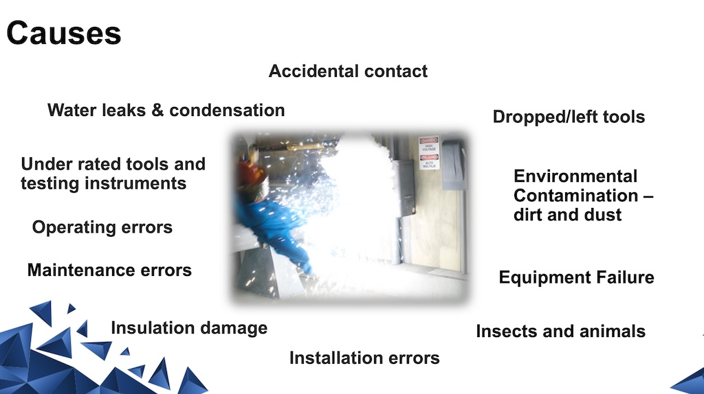
Arc faults have numerous causes that fall into two categories. One comprises intrusive environmental factors such as cabinet moisture, insulation failures, overvoltage, corroded terminals, dust, dirt, and animals, including rodents and snakes. The second category is human error such as improper work procedures, misplaced tools, loose connections, and inadvertent contact with energized components.
Inadequate maintenance practices are often contributors to both categories. As the number of arc flash incidents suggests, they are a paramount electrical safety concern, for which a range of industry safety standards have evolved.
In North America, the main safety standard for working with electrical equipment is NFPA 70E: Standard for Electrical Safety in the Workplace. It addresses electrical safety requirements for workplaces to safeguard employees during such activities as the installation, operation, maintenance, and decommissioning of electric conductors, electric equipment, signaling and communications conductors and equipment, and raceways in public and private facilities.
Under NPFA 70E, employees whose work may potentially expose them to arc flashes are required to wear arc-rated protective clothing. This clothing is made of fabric that provides thermal insulation and is also self-extinguishing to minimize burns, as prescribed by ASTM F 1506-08, Standard Performance Specification for Wearing Apparel for Use by Electrical Workers to Momentary Electric Arc and Related Thermal Hazards.
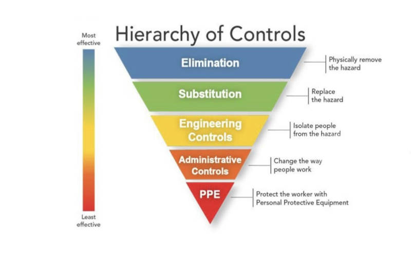
OSHA has said that clothing conforming to ASTM 1506 complies with the OSHA 29 CFR 1910.269 (Electrical Power Generation, Transmission and Distribution) directive regarding the wearing of protective clothing that will not contribute to severity of burns. Personal protective equipment is a primary part of an arc flash injury mitigation, which can also include other equipment such as a helmet or headgear, face shield, gloves, and ear protection.
The amount of PPE required is dependent on the calculated arc flash incident energy on a worker’s body, which depends on arc current, system voltage, and duration and distance from the arc. NFPA 70E defines five categories of PPE, each category providing progressively greater protection against higher and higher energy levels. The energy levels correspond to specified “boundaries” that define the degree of danger and required protection.
The highest tops out at 40 calories/cm2 skin exposure requiring the highest levels of PPE (compared to a curable second-degree burn caused by 1.2 calories/cm2 of skin exposure). When the incident energy level goes beyond 40 calories/cm2, it becomes exceedingly difficult to provide any practical means of PPE.
Safer equipment, safer environments
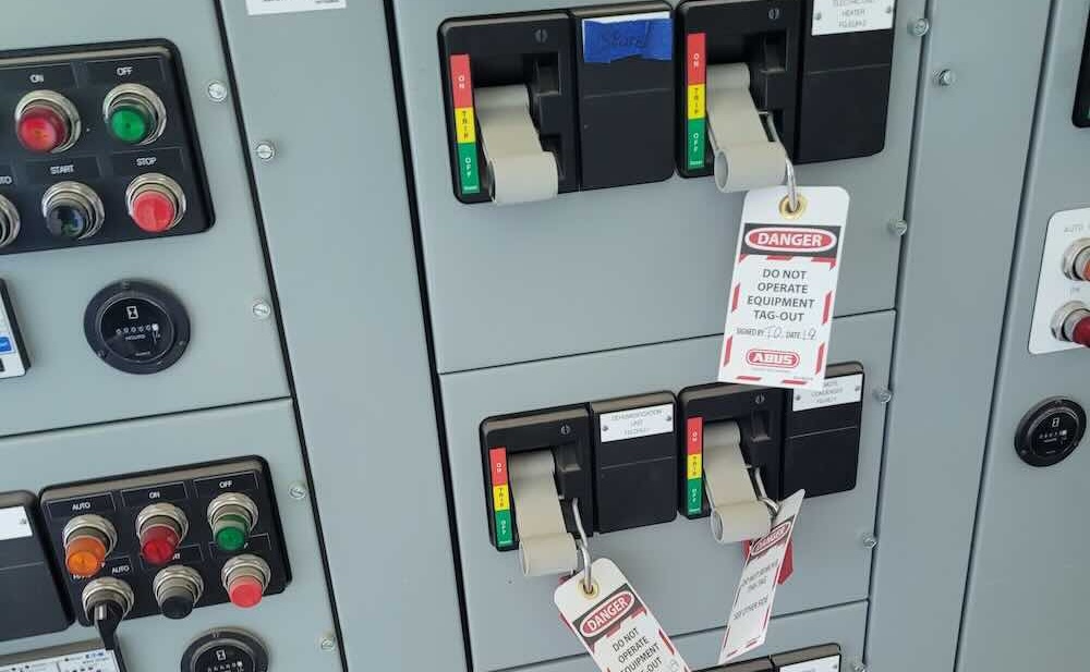
Of course, the simplest and most effective measure to prevent an arc flash is to shut off all power to the equipment to be worked on. Siemens advises that individuals should work on motor control centers (MCCs) or other electrical equipment only after all power to the equipment has been turned off. In fact, this is often done through mandated lock-out protocols.
Arc flash prevention, safety training, and PPE can only go so far in keeping workers out of harm’s way should an arc fault occur. Although PPE can provide protection from an arc flash, it still cannot protect an operator from being struck by enclosure doors blown off or open from an arc flash—or from fragments ejected from a disintegrating enclosure.
That is why manufacturers have taken steps to design arc flash hazard mitigation and arc-resistant features into their electrical equipment. These features are designed to complement each other. Arc flash mitigation features aim:
- To keep the workers beyond the arc flash boundary or,
- To shorten the arc flash duration.
Arc resistant equipment’s goal is to make sure that, in the event of an arc flash when the MCC’s doors are closed and latched, the equipment will contain the explosion, directing the arc blast, including its heat, plasma, and pressure, away from workers.
In addition, the industry has codified the performance testing of arc-resistant features according to the rigorous requirements set forth in the IEEE Guide for Testing Metal-Enclosed Switchgear Rated Up to 38 kV for Internal Arcing Faults (ANSI/IEEE C37.20.7 – 2007).
Taking Siemens type WL low-voltage switchgear as an example, arc-resistant features can include:
- ANSI/IEEE Type 2 arc resistance to protect personnel at the front, back, and sides of the equipment (Type 1 arc resistant protection only applies to the front of the cabinet.)
- UL Listed, performance tested, and classified as arc resistant per ANSI/IEEE C37.20.7
- Reinforced enclosure to withstand pressure from internal arcing faults
- Internal venting system with pressure dams and pressure vents to channel the flow of arc fault gases and vent these gases out the top of the gear and away from personnel
- Reinforced front with gaskets plus doors with extra hinges and stronger latching systems
- One-piece circuit breaker doors with insert panels for control devices such as fuses, indicating lights, and circuit breaker control switches when required
- Reinforced bolted rear covers
- Insulated bus bar system
- Shutters in circuit breaker compartments
- Sill channel with integrated arc plenum
- No configuration restrictions
- Suitable for solidly grounded or resistance-grounded configurations.
There are five criteria listed in ANSI/IEEE Std C37.20.7-2007 as follows:
Criterion 1: That properly latched or secured doors, covers, and so on, do not open. Bowing or other distortion is permitted provided no part comes as far as the position of the indicator mounting racks or walls (whichever is closest) on any assessed surface.
Criterion 2: No fragmentation of the enclosure occurs within the time specified for the test. The ejection of small parts, up to a individual mass of 60 g, from any assessed external surface above a height of two meters and from any external surface not under assessment, is accepted. No restriction is placed on the number of parts allowed to eject.
Criterion 3: Assessment of burn-through: It is assumed that any openings in the switchgear caused by direct contact with an arc will also ignite an indicator mounted outside of the switchgear at that same point. Since it is not possible to cover the entire area under assessment with indicators, any opening in the area under assessment that results from direct contact with an arc is considered cause for failure. Openings above the indicator mounting rack height (two meters) that do not cause ignition of the horizontally mounted indicators are ignored.
- Accessibility Type 1: That arcing does not cause holes in the freely accessible front of the enclosure.
- Accessibility Type 2: That arcing does not cause holes in the freely accessible front, sides, and rear of the enclosure.
Criterion 4: That no indicators ignite as a result of escaping gases. Indicators ignited as a result of the burning of paint or labels, glowing particles, and so on, are excluded from this assessment. High-speed movies or video may be used to evaluate the cause of indicator ignition.
Holes in horizontally mounted indicators caused by particles that do not ignite the indicator are ignored. Surface discoloration or charring that does not result in glowing or flaming of the indicator cloth is allowed. Any indicator cloth with surface discoloration or charring shall be replaced with new cloth before additional testing.
Criterion 5: That all the grounding connections remain effective.
Conclusion
Arc flashes present a serious safety risk. While the best protection is prevention by enforcing strict safety rules, mandating proper maintenance, and supporting that with regular safety training, advances in technology have enabled electrical equipment manufacturers such as Siemens to design and engineer much more arc-resistant safety features into their products and systems such as switchgear and MCCs.
While standards continue to evolve, they inherently follow these kinds of innovations. Nonetheless, the proper performance testing of new and innovative arc-resistant safety features cannot await standards. At the same time, it is important that the application testing of new safety features be validated by a qualified third-party like the UL to ensure that the safety features work as intended and to prevent tragic accidents.
Pablo Medina is product manager, Walt Karstens is product engineer for tiastar MCC, and Keith Flowers is program manager for WL breakers, all part of Siemens Industry Inc.


