Low power is inefficient and can also be expensive over the life of a system. Improved power factor will increase the system’s efficiency.
Low power is not only inefficient, but can also be expensive over the life of an electrical system. Many utility companies charge their industrial customers an additional demand fee if their power factor is less than a predetermined power factor value. In addition to the energy cost, there is a loss of the electrical system’s overall capacity. Low power factor will reduce the distribution system’s capacity by increasing current flow and causing voltage drops. Thankfully there are ways to improve power factor that will increase the distribution system’s efficiency and reduce energy costs associated with low power factor penalties. Before you can capitalize on these improvements, you must understand what power factor is and determine if your plant has a low power factor.
What is Power Factor (pf)?
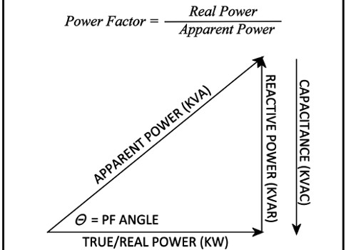
Power factor is a dimensionless number between 0 and 1 that is defined as the ratio of real power (kW) to apparent power (kVA). Real power is considered to be the work producing component. Apparent power is the product of the total current and voltage used by the load, which includes power used for electromagnetic fields. In other words, real power is the amount of power needed to perform the work in a perfect world while apparent power is the power needed to perform the work in real world conditions. This relationship is shown in figure 1. While power factor may vary over time, generally speaking, a high power factor indicates effective utilization of electrical power. A low power factor means you’re not fully utilizing the electrical power for which you are paying. A simple way to look at power factor is as a measure of how effectively electrical power is being used. A power factor of 1 (unity) is an indication of operating at a perfectly effective use of power while a 0.5 is an indication of a very inefficient use of power. A power factor of any value other than unity is caused by inductive or capacitive reactance and harmonics on the system.
What are causes of low power factor?
Low power factor can be broken into two different categories: lagging and leading. Low lagging power factor conditions can be caused by various combinations of the following inductive devices:
-
Induction motors
-
Inductive loads of fluorescent ballasts
-
Rectifiers providing a DC power supply
-
Arc welders
-
Solenoids
-
Induction heaters
-
Lifting magnets
-
Transformers.
Induction motors, including motors that are part of compressors on HVAC systems, refrigeration systems, pumps, etc., are the most common causes of low lagging pf conditions because so many are in use and often run less than a full load. Low leading power factor conditions are most commonly caused by fixed capacitors connected to the system during low load periods (off shift periods when inductive loads are turned off).
The power used for resistive loads is directly converted into heat or light. Because the voltage is assumed to be constant, the true power (kW) being used is identical to the apparent power (kVA) being supplied by the utility provider. The power factor is therefore unity or 1. In these purely resistive circuits, the current and voltage sinewave peaks occur simultaneously and are said to be “in phase.”
The power used for inductive loads is made up of two different kinds of power: “work producing power,” and “magnetizing power” which is used to sustain the magnetic field. Therefore the current flowing in an inductive circuit (unless corrected) is generally larger than is specified by the nameplate in order to produce the same amount of work. This results in reactive power and a power factor that is less than 1.
Why improve low power factor?
Low power factor means lower operating efficiency which results in a need for larger conductors (wires) and increased equipment capacity, as well as causing voltage drops as power losses increase. These equate to higher capital investment, higher expenses, and diminished distribution system performance. Power factor correction actually does not save much energy (usually less than 1% of load requirements), and even that reduction depends on how low the power factor is to begin with and how heavily loaded inductive devices are in the distribution system. However, even though energy savings are minimal, correcting power factor can bring significant savings in energy bills if the utility imposes a low power factor penalty in their rate structure, as most utilities do for industrial customers. How much your company can save through installing power factor correction methods depends on your initial power factor, the level you correct it to, motor horsepower rating versus loading, and how the penalty charge is calculated by the utility. All of these variables should be considered when determining the payback potential for different power factor correction methods.
Correcting your power factor
The first step in the process of correcting your power factor is identifying what is causing the low power factor. This information will be extremely important in determining the right approach for bringing your power factor closer to unity. There are many different strategies that can be used individually or in combination to correct low power factor. A few of these strategies are:
-
Install capacitors in the distribution system
-
Minimize operation of idling or lightly loaded motors
-
Install variable frequency drive (VFD) systems to lightly loaded induction motors
-
Install new motors that will be operated near their rated capacity
-
Replace lightly loaded motors with motors sized to be operated near their rated capacity
-
Avoid operation of equipment above its rated voltage.
The most practical and economic power factor improvement device is the capacitor. Capacitors produce capacitive reactive power, which is the opposite of inductive reactive power that is the primary driver behind low power factor values. The inductive reactive power causes the current peak to occur after the voltage peak (lagging), where the capacitive reactive power causes the current peak to occur before the voltage peak (leading). By careful selection of capacitance to add to a low power factor system, it is possible to totally cancel out the inductive reactive power. There are two methods for improving power factor using capacitors: individual load compensation and centralized compensation.
Individual load compensation typically occurs with static capacitors applied to the system on linear or sinusoidal loads. This eliminates the need for switching the capacitors because they are on when the motor is on and off when the motor is off. This avoids having the capacitance on the system while the motor is not causing the inductive reactance. This method makes it relatively simple to right-size the capacitor to counteract the motor inductive reactive power, reduce line losses and increase system capacity.
Centralized compensation typically occurs with the installation of automatically switched capacitor banks at the feeder or substation. This method commonly has a lower cost per kVAR correction. Centralized capacitor banks provide power factor correction for the entire plant and reduce or eliminate low power factor penalties. The automatic adjustment of capacitance in the system ensures the exact amount of power factor correction, eliminating over-capacitance and the resulting overvoltage.
Is power factor correction right for your plant?
In addition to the considerations already mentioned in this article, several other variables should be considered in determining the right capacitors for your specific application needs. Examples include load type, size, constancy, and capacity and of course your plant’s electric utility billing structure. The impact that a low power factor has on your plant operation and utility bill must be determined in order to compare it to the potential saving associated with the right power factor correction technique. A proper analysis also will address concerns related to harmonic distortion and transient overvoltage.
Tommy Northcott earned a BS Degree in Electrical Engineering with an emphasis in Power Systems from Tennessee Technological University. He is a Professional Engineer licensed in the State of Tennessee and a Certified Maintenance and Reliability Professional. Tommy has well over a decade of experience working with one of the largest electric utility systems in Tennessee as a Systems Engineer, Arc Flash Project Manager, Operations and Maintenance Manager, and Reliability Engineering Manager. Currently Tommy is the President of Northcott Consulting LLC and specializes in Electrical Safety Training and NFPA 70E and OSHA compliance. For more information visit www.northcottconsultingllc.com and feel free to email questions or comments to [email protected].