There are many tools on the market for historizing process data and it is often desirable to log a "set" or "group" of data together, associating many data points with a single event.

There are many tools on the market for historizing process data. These tools typically treat each point of data individually when historizing, which works great for trend screens and instrumentation reporting. However, it is often desirable to log a “set” or “group” of data together, associating many data points with a single event. This use case is particularly common with batching operations, where detailed records must be kept. This can be accomplished many different ways. One such approach, that of a so called “data pump,” is described below.
Solution overview
One of our solutions to this challenge is to create and log a “payload” of data each time an operation completed on a piece of equipment. For example, consider a bulk material addition into a mix tank. This operation contains several pieces of relevant information that can be historized, such as:
- Start Time
- End Time
- Unit (Ex: Mix Tank 102)
- Batch ID
- Event Description: (Ex: “Sucrose Addition”)
- End Condition (Completed Naturally or Manually Aborted)
- Setpoint Amount (Requested Quantity)
- Actual Amount (Delivered Quantity)
- Error % ( [Actual – Setpoint] / [Setpoint] x 100 )
- Pump Speed
- Etc.
In order to capture this information, programmable logic controller (PLC) logic is built into each operation to collect the pertinent data. At the completion of the operation, this data is then consolidated into a single record object, typically a user defined data type, in the PLC. Then this record is placed into a queue object on a “First In, First Out” basis. Elsewhere in the control system (external to the PLC), this queue is monitored for new records. As new records appear, the control system reads the appropriate data from the front of the queue, logs it to a SQL database table, and handshakes with the PLC to indicate that the record has been successfully processed.
Once the handshake is received at the PLC level, the queue is then indexed to discard the previous record and move the next record forward for processing. No records are removed from the queue until the control system acknowledges successful processing of that record. In this architecture, queued data is essentially guaranteed to be logged. Even if the mechanism processing the queue fails, the PLC (and more importantly, the automated process) can continue to run as normal. In this scenario the queue may accumulate a backlog of unprocessed records, but once the processing mechanism is brought back online they can be quickly processed. Providing a large enough queue object is important because it gives the data pump a buffer. This allows the control system to weather any interruption of communications that might occur between the PLC and the mechanism that processes the records.
Queue sizing
The queue object in the PLC should be sized large enough to accumulate a few hours’ worth of records, enabling production to continue while the communication issues are troubleshot and corrected. Once communications are restored, the processing mechanism can work through the backlog of records relatively quickly. Because the records are processed in order and include their own timestamps, any minor delays in processing are of very little consequence. Data may be delayed slightly getting from the PLC to the historical database, but the integrity (and sequence) of that data is preserved.
Alarms/faults
If data collection is mission critical, an alarm should also be implemented that triggers when the queue backs up, accumulating to some threshold of records. For example, if the queue size can support 500 records, you might choose to alarm when the queue reaches 50 or 100. Choosing an alarm threshold depends on the size of the queue, how full the queue tends to be during “normal” operation, and the anticipated response time of the control support personnel (to find and resolve any issues with the data pump).
In the scenario where the queue fills up entirely with records, any new records cannot be added to the queue (and therefore will not be logged to the structured query language (SQL) database). For this reason, it is also recommended that the PLC logic hold production (and the generation of any new records) until the issue can be resolved. Otherwise, events would be taking place that could not be properly historized. If production throughput is a higher priority than data integrity, however, integrators and end users may choose not to hold their process. In this scenario, the PLC simply discards any “overflow” data and the process continues to run regardless of the queue being full.
Additional considerations
One advantage to implementing this type of data pump is that you can “piggyback” on your record processing mechanism to trigger other actions within your control system. For example, a record being processed with a new “BatchID” may indicate that the previous BatchID for that unit is complete, meaning a report can safely be generated and distributed for the previous Batch. In another example, you may choose to flag events that consume raw material so that they can be run through an additional process that reports material usage to a customer’s ERP system.
Technical implementations
While the PLC portion of the data pump is best handled with a FIFO object and supporting logic, the mechanism that processes the FIFO of records can take many forms. A few options are listed below, roughly in order of ECS’ recommendation:
- In Ignition by Inductive Automation, with Transaction Groups offered by the SQL Bridge Module. These are configurable objects within Ignition that can be set up with triggers, handshake tags, and SQL connections to tables or stored procedures.
- In Ignition, using Gateway scoped “Tag Change Scripts” that mimic the behavior of a Transaction Group but allow for more customization at the sacrifice of some convenience. Some sample screenshots of this implementation can be seen below.
- In Rockwell Automation’s FactoryTalk View SE, with VBA code that periodically checks the PLC for new records, performs the SQL Database functions to process the data, and handshakes with the PLC.
- Via a custom written application (typically a .NET windows service or similar) that is capable of both monitoring tag values in a PLC and also executing SQL functions.
Sample implementation
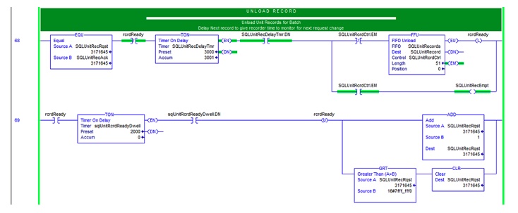
Below is a partial sample of PLC logic that manages a FIFO of records. Note that the first rung handles processing of the queue (via the FFU instruction) and not the loading of the queue with new records (via the FFL instruction). Loading of the queue would be handled elsewhere in your PLC program. The second rung adds a brief delay before incrementing the “Record_Rqst” trigger tag, which is monitored externally for change.
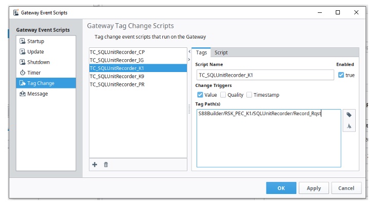
Here an Ignition Gateway Tag Change Script is shown, monitoring a “Record_Rqst” tag value within one of our S88Builder control systems. In this case the trigger is an integer tag in the PLC that is incremented any time a new record has been unloaded and is ready for processing.
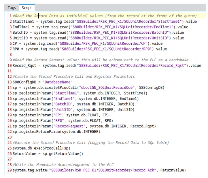
Ignition then executes the following script (reduced here for simplicity). A more complete solution would implement error handling or might be implemented in a script library rather than directly within the Tag Change script.
ONLINE
Learn more about ECS Solutions
