There is only one time to correct water hammer – immediately.
Water hammer is never normal – it is abnormal
Water hammer is not only a system issue; it is primarily a safety issue. Understanding the nature and severity of water hammer in a steam and condensate system allows facilities to avoid its destructive forces. A greater understanding should also help with the introduction of preventative measures into system designs, steam system startups, maintenance, and installations. This will additionally help provide maximum safety for personnel, reduce maintenance costs, and reduce system downtime.
Water hammer, in its most severe form, can injure or even cause fatalities to plant personnel.
Unfortunately, high percentages (82%) of steam systems experience some type of water hammer. Many operators mistakenly believe that water hammer is unavoidable and a natural part of steam and condensate systems. This is entirely false. In properly designed and correctly operated systems, water hammer in any form will not occur. It is possible to have high-pressure steam systems operating without water hammer, with a long operational life from the steam components.
Where does water hammer occur?
Water hammer can occur in any steam or condensate line. Its effects can be even more pronounced in heterogeneous or condensate bi-phase systems. Condensate bi-phase systems contain two states, the liquid (condensate) and a vapor (flash or generated steam). The bi-phase condition exists in a steam system where condensate coexists with generated steam or flash steam. Typical examples include heat exchangers, tracer lines, steam mains, condensate return lines and sometimes, pump discharge lines.
A common example of water hammer occurs during the startup or energizing of a steam system. If the steam line is energized too quickly without proper warm-up time, and the condensate created during startup is not properly removed, water hammer will result.
Effects of water hammer
You cannot underestimate the effect of water hammer. It has been documented to:
- Collapse the elements in all designs of steam traps;
- Overstress pressure gauges;
- Bend internal system mechanisms;
- Crack steam trap bodies;
- Rupture pipe fittings;
- Cause valve failures;
- Cause heat exchanger equipment tube failures;
- Break pipe welds and even rupture piping systems; and
- Cause failure of pipe supports.
When water hammer is severe, it can result in not only damage to equipment, but also possible injury to plant personnel.
Water hammer may be occurring and yet silent to personnel. Water hammer is not always accompanied by audible noise that can be heard by the human ear. For example, a small steam bubble collapsing creates a thermal shock not heard by the human ear. However, damage to steam and condensate components still occurs.
The continuing banging or audible sounds accompanying water hammer is the system’s way of communicating a problem. Personnel should interpret the sounds as an alarm indicating that something in the system is wrong and needs to be corrected before damage is done.
Evidence gathered while conducting root cause analysis on steam component failures suggested water hammer caused 67% of the premature component failures.
Conditions causing water hammer
Four conditions are identified as causes for violent water hammer reactions:
- Hydraulic shock
- Thermal shock
- Flow shock
- Differential shock
Hydraulic shock
Hydraulic shock causes a small percentage of the water hammer problems found in a steam system. The example of a household faucet best describes this cause.
When the faucet in a home opens, a solid shaft of water is moving through the pipes from the point where it enters the house to the outlet of the faucet. This could be 200 lbs of water moving at 10 ft per sec, or about seven miles per hour.
When the faucet suddenly shuts, it could be compared to a 200-lb hammer coming to a stop. There is a noticeable bang heard in the system when the faucet is closed. This shockwave sound is similar to a hammer hitting a piece of steel. The shock pressure wave of about 300 psi is reflected back and forth from end to end until the energy is dissipated in the piping system.
The same action can take place in the suction or discharge piping in a steam and condensate system. Pumps are often installed with check valves. As the pump starts and stops, hydraulic shock can occur as the flow rapidly stops and the check valves restrict the flow in one direction. Slow closure of the valve, just like slowly closing a faucet, is the solution to this problem. When a column of water is slowed before it is stopped, its momentum is reduced gradually; therefore, damaging water hammer will not be produced.
Thermal shock
One pound of steam at 0 psi occupies 1,600 times the volume of a pound of water at atmospheric conditions. This ratio drops proportionately as the condensate line pressure increases. When the steam collapses, water accelerates into the resulting vacuum from all directions with great speed.
In bi-phase condensate systems, steam bubbles may be introduced below the level of condensate in a condensate line. For example, a branch line from a steam trap may be piped to the bottom of a condensate main header. The pressure in the condensate line (lower pressure = lower temperature) is lower than the flash steam temperature. The condensate cools the flash steam bubble and the steam bubble collapses immediately. While collapsing, it creates a void in the volume of the pipe and condensate rushes to fill this void, thus causing an audible pinging sound.
Flow shock
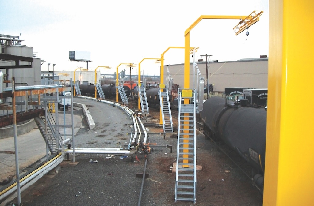
Flow shock is most commonly caused by lack of proper drainage ahead of a steam line isolation valve or steam control valve. For example, consider a steam line isolation valve (typically used with pipe of 3 in. or larger) opened without the use of a warm up. When the large valve opens, steam rushes down a cold pipe producing a large quantity of condensate at high velocity. This condensate will continue to build in mass as it travels along the pipe, creating a large wave of condensate. The wave will travel at a high velocity until there is a sudden change in direction, possibly an elbow or valve in the line. When the condensate changes direction, the sudden stop will generate water hammer.
When a steam control valve opens, a slug of condensate enters the equipment at a high velocity. This produces water hammer when the condensate impinges on the heat exchanger tubes or walls. Additionally, water hammer from thermal shock will result from the mixing of steam and condensate that follows the relatively cooler condensate.
The above CAD print is the standard installation of an isolation valve in a steam system. Two main points are the warm-up valve and the drip leg pocket with a steam trap ahead of the isolation valve. The installation will prevent water hammer during startup, and it will also promote long valve life.
Differential shock
Differential shock, like flow shock, occurs in bi-phase systems. It occurs whenever steam and condensate flow in the same line, but at different velocities. This is commonly seen in condensate return lines.
In bi-phase systems, velocity of the steam is often 10 times the velocity of the liquid. If condensate waves rise and fill a pipe, a seal is formed temporarily between the upstream and downstream side of the condensate wave. Since the steam cannot flow through the condensate seal, pressure drops on the downstream side. The pressure differential now drives the condensate seal at a high velocity downstream and accelerates it like a piston. As it is driven downstream it picks up more liquid, which adds to the existing mass of the slug, and the velocity increases.
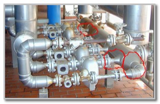
Just as in the example shown, the slug of condensate gains high momentum and will be forced to change direction due to a tee, elbow, or valve in the line. The result is usually great damage when the condensate slug pounds into the wall of a valve or fitting while changing direction.
Since having a bi-phase mixture is possible in most condensate return lines, correctly sizing condensate return lines becomes essential.
Condensate normally flows at the bottom of a return line with the assistance of gravity. Condensate flows naturally because of the pitch in the pipe, and also because the higher velocity flash steam above pulls it along. The flash steam moves at a higher velocity because it moves by differential pressure.
Flash steam occurs in return lines when condensate discharges into these lines that are operating at a lower pressure. The lower pressure causes a percentage of the condensate to flash back to steam at the given saturation pressure. If the lines are also undersized, additional pressure is created in the line. This pressure pushes the flash steam at relatively higher velocities toward the condensate receiver, where it is vented to atmosphere.
Heat loss of the flash steam while moving in the line causes some of the flash steam to condense, which contributes to this pressure difference and amplifies the velocity. Because the flash steam moves faster than the condensate, it makes waves. As long as these waves are not high enough to touch the top of the pipe and do not close off the flash steam’s passageway, no problem exists. This is why larger sized condensate return lines are preferred.
To control differential shock, you must prevent the condensate seal from forming in a bi-phase system. Steam mains must be properly trapped and condensate lines must be properly sized. The length of horizontal lines to the trap’s inlet should be minimized.
Steam main drainage is one of the most common applications for steam traps. It is important that water is removed from steam mains as quickly as possible, for safety reasons, and to permit greater plant efficiency. Water build-up can lead to water hammer.
Preventing or resolving water hammer
There are a variety of design or system changes that can be implemented to prevent or eliminate water hammer:
- Ensure proper training of plant personnel.
- Correct steam and condensate design practices.
- Create and enforce documented standard operation procedures (SOPs) for steam system startups and shut downs.
- Have installation standards for steam components.
- Properly specify and place steam line drip steam traps on the steam system.
- Correct condensate connections of branch lines to the main condensate line and enter only on the top,
- Use steam traps that are properly sized and appropriate for the application.
- Use warm-up valves on steam line isolation valves larger than 2 in. Do not “crack open” large steam isolation valves with the hope of avoiding condensation-induced water hammer. This will not guarantee safe operation.
- Check or repair the pipe insulation. It saves energy and reduces accumulation of condensate in the piping system.
- Condensate line sizing is crucial to ensure proper operation of the steam system. Under-sizing the condensate lines is one of the largest contributors to water hammer.
- A system that has a modulating control valve should have a drip leg trap upstream of the valve to remove condensate during a closed condition for the valve.
- Always gravity drain away from the process applications with a modulating control valve.
- Condensate can be drained into a pressurized condensate return line.
- Properly label the steam and condensate lines.
- Remove abandoned steam and condensate lines from the system.
- Implement a proactive maintenance program.
For more information, visit www.swagelokenergy.com.
The above material is part of Swagelok Energy Advisors’ series of Best Practice papers, authored by Kelly Paffel. Kelly is a recognized authority in steam and condensate systems. He is a frequent lecturer and instructor on the technical aspects of steam systems. In addition, Kelly has published many papers on the topics of steam system design and operation. Over the past 30 years, he has conducted thousands of steam system audits and training sessions in the United States and overseas, which has made Kelly an expert in trouble-shooting actual and potential problems in the utilities of steam. Kelly is a member of the U.S. Department of Energy’s (DOE) Steam Best Practices and Steam Training Committees.
www.swagelokenergy.com
Swagelok Company