Circuit protection is crucial for the new wave of value-added devices.
Smart meters are integral to a growing number of industrial utilities applications, including gas and water meters, energy management, and others. Smart meters offer a wide variety of advantages for both utility companies and their customers, including support for real-time billing, fault identification and management, load-side demand monitoring and management, theft/tamper detection, and demand analysis.
The in-depth data these meters provide allow utility companies to monitor energy usage, control demand usage by remote connect/disconnect, identify tampering and raise alarms, etc. Utility companies also can give users advance warning of upcoming/unscheduled power outages and restorations, and diagnose and correct problems before meters fail. In addition, smart meters provide customers much of the information needed to perform real-time usage analysis so that they can begin controlling their usage in a timely way, understand power quality, and protect the connected loads in case of overvoltages or overloads.
Complex circuits require protection
Smart meters are bidirectional, communication-based devices that incorporate complex electronic circuits for controlling the measurement of power (or gas or water) consumption as well as for handling the communication and other smart functions required. As their complexity increases, so does their vulnerability to circuit threats like transients, electrostatic discharges, power quality disturbances, etc. To ensure these meters continue to work, even in hostile operating conditions, robust circuit-protection technologies are essential.
Different types of smart meters will face various threats. For example, the biggest threats to electricity meters are input transients and power line disturbances. However, water and gas meters need protection for their batteries. Similarly, energy-monitoring devices that have a human-machine interface (HMI) need to be protected against electrostatic discharges (ESDs). All of these systems employ different communication interfaces, and many of them also need circuit protection.
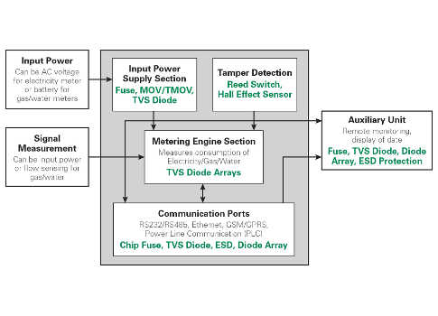
The following section investigates the specific protection requirements for each block of the smart meter solution shown in Figure 1.
Input power supply section: If it’s an electricity meter, then it is powered by input mains, which are highly prone to high energy transients arising from lightning or grid disturbances. Metal oxide varistors (MOVs) are used to protect against these transient surge events. To protect the wiring from fire hazards in case catastrophic damage in the power supply causes a short circuit, a fuse is also used at the power supply’s input front end.
Metering engine section: A microcontroller or digital signal processor is typically used for energy measurement and processing purposes. Although the power supply to this microcontroller is protected from transient surges, the analog signal-sensing pins of the microcontroller are still connected to the input supply for measurement of voltage and current. Although these signal pins normally have a high value of resistances and capacitors connected for filtering purposes, some fast-rising transients can pass these filter stages and reach the microcontroller, which is very sensitive to transients. To prevent damage to the microcontroller, very small transient-protection diodes are used on the signal pins to clamp any incoming transients to safe levels.
Communication ports: Depending upon the meter application, a number of communication ports might be used, including RS-232/RS-485/Ethernet/GSM-GPRS, power line communication (PLC) or optical ports. Because each of these port types has different operating speeds and specifications, they will need different protection schemes. (See sidebar for an example).
Tamper detection: Utility companies use smart meters to track usage so they can charge users for their consumption. However, this causes some users to try to tamper with the meter and manipulate the readings. As a result, these meters are typically designed with a host of tamper-detection techniques.
The simplest, most common tampering technique is to open the meter cover and damage it. By using a reed switch with a magnet or microswitch in the design, this sensor detects when the cover is opened and sends a trigger to the microcontroller. After recognizing the tamper attempt, the microcontroller notifies monitoring support staff at the utility company who, in turn, can impose a tampering penalty on the user.
Another method of meter tampering involves bringing a magnet close to the meter’s body, which can either cause the magnetic transformer to saturate or affect other components. When a Hall effect sensor is employed in the design, it detects the field of the magnet and gives a trigger to the microcontroller to record the tamper event and inform the utility company.
Another severe tampering technique involves causing an ESD discharge to the meter body using a spark plug or CRT-EHT generator. In this case, the meter enclosure is made using plastic to fully isolate the electronics circuit from the external world and minimize the impact of this ESD discharge. The microcontroller’s power supply and signal-sensing pins will have ESD protection diodes to protect the microcontroller from any ESD discharge that still gets coupled to it. With the first two tampering techniques, the microcontroller can send details on the tampering attempt to a control/monitoring station for assessing a penalty or just to protect the meter from getting damaged.
Auxiliary power supply section: Smart meters sometimes have an extension unit that goes into the user’s home while the main meter is installed at a centralized location in the building. For these applications, the home extension unit may have a Power over Ethernet (PoE) adapter. This communication cable requires additional protection because it can be susceptible to induced surges in the building.
Specific protection requirements
Electrical power meters are susceptible to input transients and surges generated either by lightning events or power quality disturbances. These transients, which can reach 30 kV in magnitude, depend on a variety of factors including geographical location, types of loads connected in the vicinity, etc. MOVs are primary devices used for protecting against these surges. The required level of surge immunity dictates the rating and size of the MOV. For basic surge protection between 2 kV and 4 kV, a 14-mm MOV might work. However, for protection levels of 30 kV, a larger 32-mm or 34-mm MOV might be needed.
Because they are passive devices with limited lifetimes, MOVs have several inherent problems associated with their end-of-life stage. For example, once they reach their end of life, they can cause damage to themselves and pose a threat to their electronic circuit. The MOV can withstand only so many surge strikes before failing, and this surge strike capability depends on the MOV disc size and the magnitude of the surges the MOV is designed to absorb.
So, while selecting an MOV, along with considering the peak surge immunity needed, it’s also important to take into account the system’s expected lifetime. For example, consider a system that’s meant to last 5 years and requires 6 V protection. Even if a 20-mm MOV might meet a 6-kV/3-kA, 15-strike criteria, a 25-mm or larger MOV would be used to provide the ability to withstand more surge strikes over the lifetime of the meter. Adequate derating of the MOVs used is needed to ensure the system lasts for its desired lifetime.
Some of the newer specifications also require that these MOVs are protected against end-of-life failures. For these applications, thermally protected MOVs (TMOVs) are used (Figure 2) to continue protecting the circuit during their lifetime. Once they reach the end-of-life stage, they disconnect themselves from the circuit to prevent catastrophic damage. TMOVs can also have an indication feature to alert the meter that the protector has failed and needs replacement.
TMOVs have an integrated thermal fuse
TMOVs ensure that the MOV is disconnected from the supply when it reaches end-of-life stage. Indicating TMOVs (iTMOVs) also indicate when replacement is required.
In designs where fast-rising transients can also damage the power supply section, transient voltage suppression (TVS) diodes are often used in conjunction with MOVs. These devices clamp the fast-rising transients while the front-end MOVs absorb the bulk of the high energy in those transients.
Meters used in water and gas utility applications normally have a fixed internal battery that is sized to last for 5 to 10 years. The most commonly used battery chemistry is lithium-ion (Li-ion). Because these batteries have significant capacities, a normal or a resettable fuse is used to protect against short-circuit failures caused by faults in the circuit.
The most critical resource in these meters is the battery life, which must be preserved and protected to extend the life of the meter. These meters derive their sensing signal from a magnetized encoder and by using a reed-switch sensor; the signal is fed to the microcontroller (Figure 3). The smart meter can be designed so that the microcontroller turns on only when the reed switch senses a pulse. After it records the pulse count, it goes back into sleep mode, which helps extend the battery life so that the meter can last longer.
Designing a smart electrical power meter
To illustrate the process involved in designing a single-phase smart electrical meter, consider an example using the following specifications:
Input surge protection:
Combination wave: Differential mode 15 strikes of open-circuit voltage (1.2 µS/50 µS) 10 kV with short-circuit current (8 µS/2 0µS) 5 kA
Ringwave: 100 kHz, 0.5 µS, 6 kV/0.5 kA
In this example, MOVs will be used to protect against surges. Because the combination wave has more energy than the ringwave, the design must consider its requirements. For protection against 15 strikes of a 10-kV/5-kA surge, a 20-mm MOV can be used. However, if the meter is expected to withstand many more surges than that over its lifetime, then an MOV with a 25-mm or larger disc size would be preferred.
A TMOV should be selected if end-of-life protection is also needed. Because it’s a single-phase design, the input voltage would be 220 VAC nominal and a maximum of either 265 VAC or 277 VAC. Therefore, a 275 V or 320 VAC MOV can be used. If the meter is expected to withstand twice the input voltage (up to 440 VAC), then a higher-voltage 460 VAC MOV should be used so that the TMOV does not activate or fail during test conditions.
To detect the opening of the meter’s cover, either a reed switch or a microswitch can be used. To detect if a high power magnet is being brought close to the meter, a Hall effect sensor can be used.
GPRS, PLC, and RS-485 communication interfaces require different types of protection devices. For example:
- A SIM card requires a 4- or 5-channel device
- An RS-485 interface requires a dual-channel device with a higher operating voltage
Considering the advantages of their detailed monitoring and management functions, smart meters seem destined to play a significant role in everyday life. The level of investment required to install these meters is significantly higher than for conventional meters, so it’s critical that they offer longer lifetimes and greater reliability. That means building in robust circuit protection will be essential.
Navneet Vinaik is the field applications manager for the India & South Africa business unit at Littelfuse. He can be reached at [email protected].